Cam-driven clamping feeder

A technology of clamping feeding and cams, which is applied in thin material processing, winding strips, transportation and packaging, etc. It can solve the problems of low synchronization of actions, wear of copper strip surface, unstable structure, etc., and achieve space utilization. Sufficient, reduced installation requirements, reduced contact area

Pending Publication Date: 2021-04-23
王浩名
View PDF0 Cites 0 Cited by
  • Summary
  • Abstract
  • Description
  • Claims
  • Application Information

AI Technical Summary

Problems solved by technology

[0002] Generally speaking, there are many types of feeders, the efficiency of feeding is also different, and the stability of feeding is also different. At present, for feeding workpieces such as copper strips, it is necessary to consider the stable and reliable transportation of copper strips. In the process, the existing machine is easy to cause the surface wear of the copper strip. In addition, the structure is unstable when the feeding is accelerated, and the failure rate is high. The main reason is that the synchronization of the action is not high and the mechanical wear is serious.

Method used


Image

  • Cam-driven clamping feeder
  • Cam-driven clamping feeder
  • Cam-driven clamping feeder

Examples


Embodiment

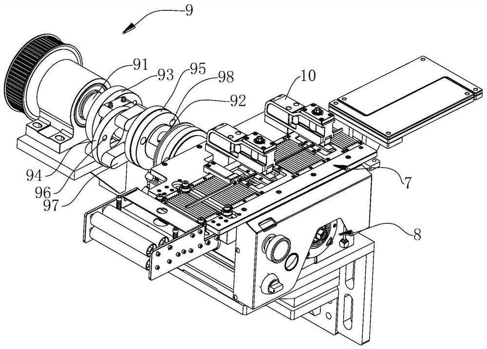
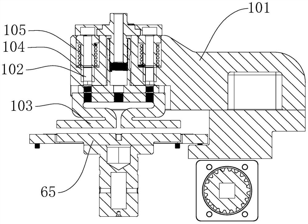
[0036] A cam-driven clamping feeder, refer to figure 1 As shown, it includes a feeding needle roller platform 7 , a feeding host 8 , an eccentric transmission mechanism 9 , and a floating manipulator 10 . The feeding needle roller platform 7 is assembled and carried on the top of the feeding host 8 . refer to figure 2 , the structure of the feeding needle roller platform 7 is mainly assembled by the needle roller seat 71 and the needle roller shaft 72, and the needle roller shaft 72 is assembled on the needle roller seat 71 so that the needle roller shaft 72 is higher than the surface of the working platform to realize the rolling of the needle roller shaft 72 Transfer artifacts. It needs to be explained here that the product of this design is used for conveying belt-shaped workpieces, such as copper strips, metal sheets or metal strips. Due to the rolling friction method, the friction force is small and the impact on the surface of the workpiece is less.

[0037] The wor...


PUM


Abstract

The invention discloses a cam-driven clamping feeder, belongs to the technical field of feeders, solves the problems of working efficiency and reliability, and adopts the technical scheme that the cam-driven clamping feeder comprises a feeding roller pin platform, a feeding main machine, an eccentric transmission mechanism and a floating manipulator. The eccentric transmission mechanism is provided with an input shaft used for being connected with a power source and an output shaft used for being connected with the feeding main machine; the input shaft and the output shaft are eccentric; the feeding main machine comprises a machine box, a main shaft, an eccentric swing mechanism, a sliding mechanism and a parallel four-bar mechanism; the main shaft is connected with the output shaft and drives the eccentric swing mechanism and the parallel four-bar mechanism at the same time; the eccentric swing mechanism drives the sliding mechanism to act; the floating manipulator is fixed onto the feeding roller pin platform and located above the sliding mechanism; and the sliding mechanism and the parallel four-bar mechanism are matched with the floating manipulator to conduct clamping and moving actions, so that the effects of efficient material conveying, stability and reliability are achieved.

Description

technical field [0001] The invention relates to the field of feeders, in particular to a cam-driven clamping feeder. Background technique [0002] Generally speaking, there are many types of feeders, the efficiency of feeding is also different, and the stability of feeding is also different. At present, for feeding workpieces such as copper strips, it is necessary to consider the stable and reliable transportation of copper strips. In the process, the existing machine is easy to cause the surface wear of the copper strip. In addition, the structure is unstable when the feeding is accelerated, and the failure rate is high. The main reason is that the synchronization of the action is not high and the mechanical wear is serious. Contents of the invention [0003] The purpose of the present invention is to address the deficiencies of the prior art, at least to a certain extent to solve the technical problems in the related art, to provide a cam-driven clamping feeder, so as to...

Claims


Application Information

Patent Timeline
Patent Type & Authority Applications(China)
IPC IPC(8): B65H20/02B65H20/16B65H79/00
CPCB65H20/02B65H20/16B65H79/00B65H2301/443246B65H2301/44338
Inventor 王浩名王伫多
Owner 王浩名
Why Eureka
Try Eureka