
Ash-cleaning mechanical air cooler

A technology of mechanical air cooling and ash cleaning mechanism, which is applied in the field of ash cleaning type mechanical air cooler and high temperature flue gas cooling, can solve the problems of inability to eliminate, low heat transfer coefficient and large cooling area.

Inactive Publication Date: 2003-11-05
WUXI XUELANG ENVIRONMENTAL TECH CO LTD
View PDF0 Cites 0 Cited by
  • Summary
  • Abstract
  • Description
  • Claims
  • Application Information

AI Technical Summary

Problems solved by technology

The round tube plate structure is prone to dust accumulation, which cannot be eliminated, has a low heat transfer coefficient, and has a large cooling area; the structure is huge, heavy, and the manufacturing cost is high. , dust removal has brought a lot of inconvenience

Method used


Image

  • Ash-cleaning mechanical air cooler
  • Ash-cleaning mechanical air cooler
  • Ash-cleaning mechanical air cooler

Examples


Embodiment Construction

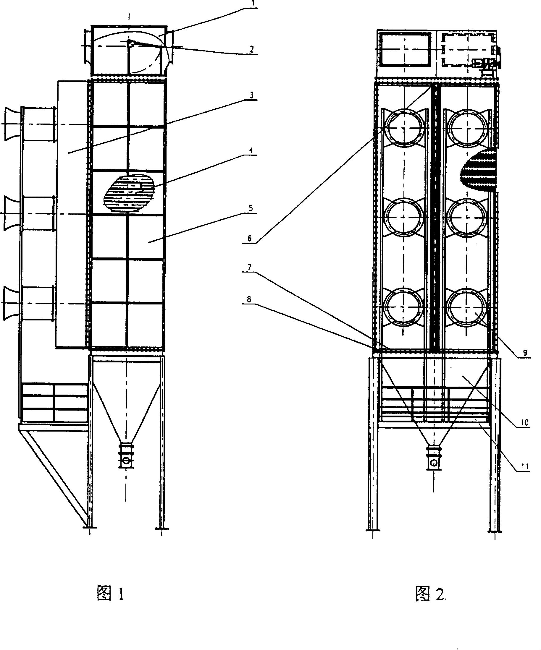
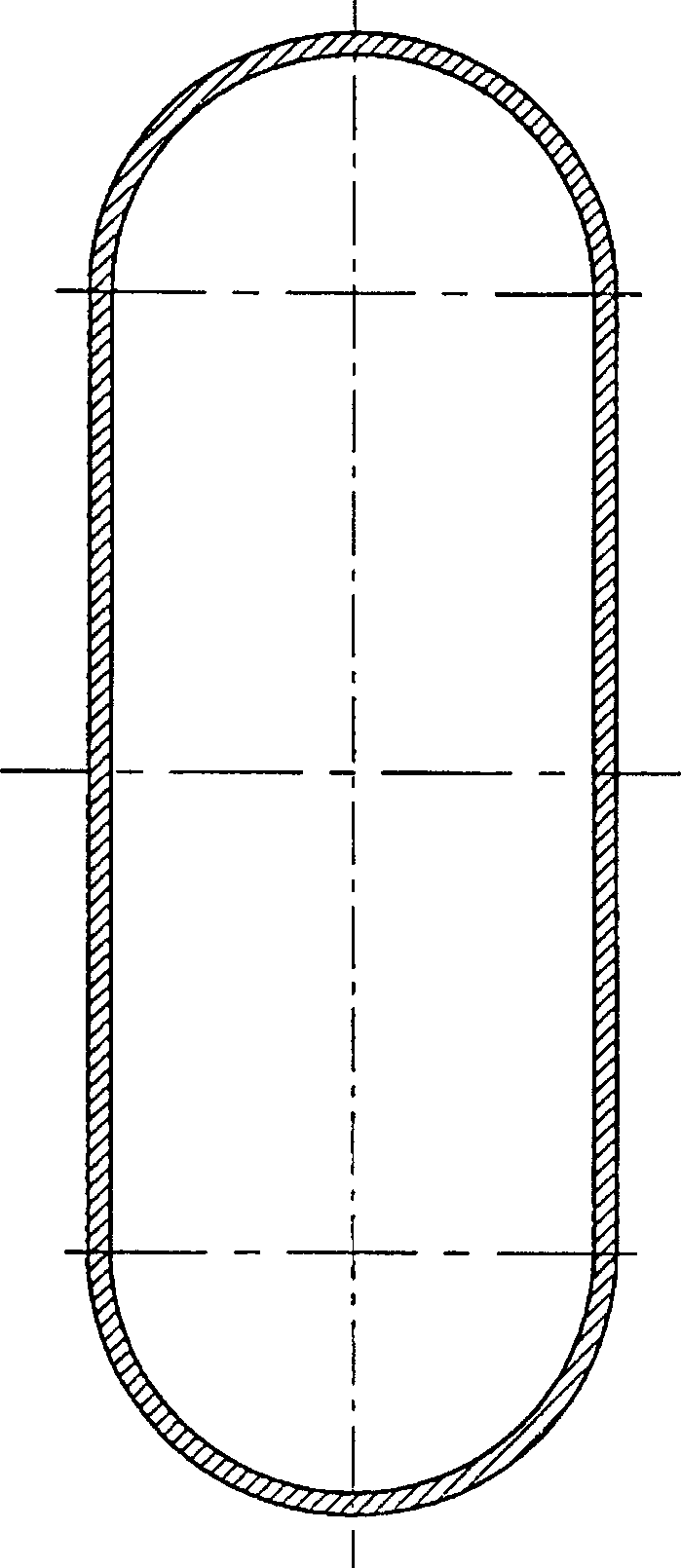
[0012] The main part of the present invention is mainly composed of header 1, dust cleaning mechanism 2, fan 3, heat dissipation pipe 4, side wall plate 5, middle partition plate 6, ash bucket ring beam 7, mixed flow fan 9, ash bucket part 10, support platform 11 composed of. The header box 1 and the dust cleaning mechanism 2 are connected and assembled together for the entry and exit of flue gas. These two parts are installed on the heat dissipation pipe 4. An air inlet is formed on the back of the right side of the header box 1. Side wall panels are installed on both sides of the heat dissipation pipe 4. 5. An intermediate partition 6 is installed in the middle, and a fan 3 and a plurality of mixed-flow fans 9 are installed on the other side of the heat dissipation pipe 4 for blowing cooling air into the heat dissipation pipe 4 . A plurality of heat dissipation pipes 4 are used to form a heat dissipation pipe group, and several heat dissipation pipes 4 are installed in paral...


PUM


Abstract

The invention relates to a dust-cleaning mechanical air cooler, which is mainly used for cooling high-temperature flue gas in smelting and electric power industries, and belongs to the technical field of cooling equipment. It mainly includes heat dissipation pipes, wall panels, middle partitions, fans, ash hopper ring beams, ash hopper parts, and support platforms. superior. The invention has the advantages of simple structure, small volume, light weight, and low manufacturing cost; high-temperature flue gas goes out of the pipe, and cooling air goes inside the pipe, which facilitates dust removal, reduces wind resistance loss, and improves cooling efficiency; Ash, prolonging the service life.

Description

Technical field: [0001] The invention relates to a dust-cleaning mechanical air cooler, which is mainly used for cooling high-temperature flue gas in smelting and electric power industries, and belongs to the technical field of cooling equipment. Background technique: [0002] Before the present invention was made, in the prior art, the air cooler used for cooling high-temperature flue gas in the smelting and electric power industries mainly used the header to be directly installed on the heat dissipation pipe, and the round pipe heat dissipation pipe was vertically installed on the ash bucket ring beam On the top, there are wall panels on both sides of the cooling pipe, and a fan on the other side. The ash hopper parts are installed under the ash hopper ring beam. The bracket platform is used to fix the above parts, and its structure is welded as a whole. When working, the high-temperature flue gas passes through the round tube plate type through the cooling air outside the...

Claims


Application Information

Patent Timeline
Patent Type & Authority Patents(China)
IPC IPC(8): F28G3/06
Inventor 杨建平徐慎山
Owner WUXI XUELANG ENVIRONMENTAL TECH CO LTD
Learn More