Injection molding equipment for automobile part production

A technology of injection molding equipment and spare parts, applied in the field of auto parts, can solve problems such as reducing work efficiency, reducing the practicability of injection molding machines, and affecting the quality of finished products

Pending Publication Date: 2021-04-23
江苏兴业汽车饰件有限公司
View PDF0 Cites 2 Cited by
  • Summary
  • Abstract
  • Description
  • Claims
  • Application Information

AI Technical Summary

Problems solved by technology

[0003] After the existing injection molding machine is used for a long time, plastic remains in the mold, which affects the quality of the finished product, thereby reducing the practicability of the existing injection molding machine. Not only that, the existing injection molding machine does not clamp and fix after the mold is closed Because of the structure of the raw material, after the raw material is heated and injected into the mold, due to the temperature rise in the mold and the pressure increase, the mold that has not been clamped and fixed is likely to produce a gap at the seam under high pressure, so that the finished product needs to be removed after demoulding. Manual repair of plastic leaks at joints increases unnecessary processes and reduces work efficiency

Method used


Image

  • Injection molding equipment for automobile part production
  • Injection molding equipment for automobile part production
  • Injection molding equipment for automobile part production

Examples


Embodiment Construction

[0026] The present invention is described in further detail now in conjunction with accompanying drawing. These drawings are all simplified schematic diagrams, and only illustrate the basic structure of the present invention in a schematic manner, so they only show the configurations related to the present invention.

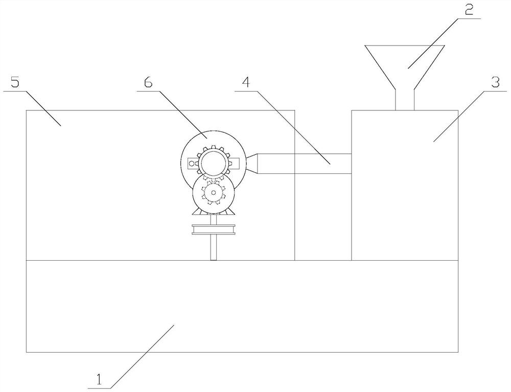
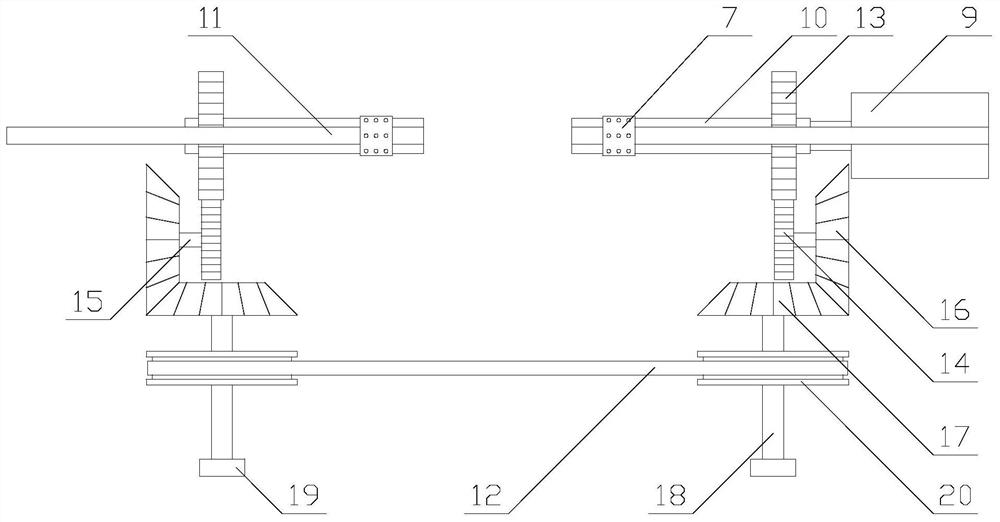
[0027] Such as Figure 1-4 As shown, an injection molding equipment for the production of auto parts, including a base 1, a hopper 2, a heating chamber 3, a feeding pipe 4 and a molding chamber 5, the heating chamber 3 and the molding chamber 5 are respectively arranged on the base 1 On both sides of the top of the molding chamber 5, there is a mold 6, the feeding pipe 4 is arranged horizontally, the heating chamber 3 communicates with the mold 6 through the feeding pipe 4, and the feeding hopper 2 is arranged in the heating chamber 3, the hopper 2 communicates with the heating chamber 3, the molding chamber 5 is provided with a fixing mechanism and two clampin...


PUM


Abstract

The invention relates to injection molding equipment for automobile part production, which comprises a base, a feeding hopper, a heating chamber, a material conveying pipe and a forming chamber. The heating chamber and the forming chamber are respectively formed on both sides of the upper portion of the base; a die is arranged in the forming chamber; a material conveying pipe is transversely arranged; the heating chamber communicates with the die through the material conveying pipe; the feeding hopper is arranged above the heating chamber; the feeding hopper is communicated with the heating chamber; a fixing mechanism and two clamping blocks are arranged in the forming chamber; the two clamping blocks are respectively arranged on both sides of the die; the fixing mechanism is arranged at the bottom in the forming chamber; and the fixing mechanism is connected with the clamping blocks. According to the injection molding equipment for automobile part production, the die can be clamped and fixed through the fixing mechanism, so that the stability of the die is improved, the procedure of repairing leaked plastic at a joint colse is reduced; and moreover, the cleaning range of a spraying nozzle is enlarged through the fixing mechanism, and the practicability of the injection molding equipment is improved.

Description

technical field [0001] The invention relates to the field of auto parts, in particular to an injection molding device used for the production of auto parts. Background technique [0002] In the production process of auto parts, raw materials need to be heated and formed. At this time, injection molding machines are needed. Injection molding machines are also known as injection molding machines or injection machines. It is the main molding equipment for making thermoplastics or thermosetting plastics into various shapes of plastic products using plastic molding molds. Divided into vertical, horizontal, all-electric. The injection molding machine heats the plastic, applies high pressure to the molten plastic, and makes it shoot out to fill the mold cavity. [0003] After the existing injection molding machine is used for a long time, plastic remains in the mold, which affects the quality of the finished product, thereby reducing the practicability of the existing injection m...

Claims


Application Information

Patent Timeline
Patent Type & Authority Applications(China)
IPC IPC(8): B29C45/17B29C33/72B08B3/02
Inventor 谷勇居勇金英培成志鹏陆加俊张瑞芳
Owner 江苏兴业汽车饰件有限公司
Why Eureka
Try Eureka