
Rotary joint for antenna erection

A technology of rotating joints and joints, which is applied to the structural connection of antenna grounding switches, waveguide-type devices, electrical components, etc., can solve the problems of antenna and receiving and transmitting power limitations, and the number of microwave signal channels is small. The effect of large capacity and long life

Active Publication Date: 2021-04-20
ANHUI HENGNUO ELECTROMECHANICAL SCI & TECH
View PDF6 Cites 0 Cited by
  • Summary
  • Abstract
  • Description
  • Claims
  • Application Information

AI Technical Summary

Problems solved by technology

[0004] The purpose of the present invention is to provide a rotary joint for antenna erection to solve the problem that the existing radar antenna feed system proposed in the above background technology can use a relatively small number of microwave signal channels, resulting in the antenna and receiving and The problem of limited transmission power

Method used


Image

  • Rotary joint for antenna erection
  • Rotary joint for antenna erection
  • Rotary joint for antenna erection

Examples


Embodiment Construction

[0022]Next, the technical solutions in the embodiments of the present invention will be apparent from the embodiment of the present invention, and it is clearly described, and it is understood that the described embodiments are merely embodiments of the present invention, not all of the embodiments.

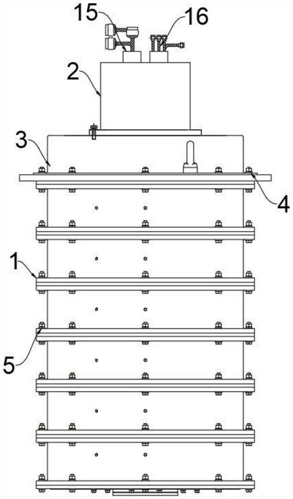
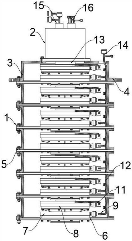
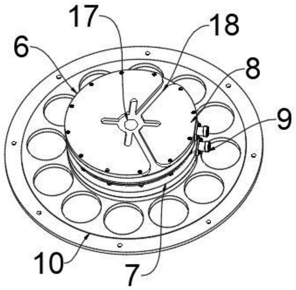
[0023]SeeFigure 1-5One embodiment of the present invention is provided: a rotary joint for an antenna, including a seven-way rotating joint mechanism 1 and a bus loop 2, the bus loop 2 transmits signal channels, and the transmission operating current and voltage are not large. Therefore, in the form of a brush wire bus ring structure, the bus ring 2 is disposed at the top of the seven-way rotating joint mechanism 1, and the bus loop 2 and the seven rotating joint mechanism 1 are connected by bolt, and the seven-way rotating joint mechanism 1 includes a single joint set. 3, and the single joint sleeve 3 has seven, the outer side of the single-joint sleeve 3 is provided with the bracket pag...


PUM


Abstract

The invention discloses a rotary joint for antenna erection, relates to the technical field of antenna joints, and aims to solve the problem that the number of microwave signal channels capable of being used by an antenna feed system of an existing radar in the prior art is relatively small, so that an antenna and receiving and transmitting power are limited. A collecting ring is arranged at the top of a seven-way rotary joint mechanism, the collecting ring is connected with the seven-way rotary joint mechanism through bolts, the seven-way rotary joint mechanism comprises seven single-way joint sleeves, the outer sides of the single-way joint sleeves are provided with support hinge edges, the support hinge edge and the one-way joint sleeves are arranged to be of an integrated structure, locking bolts are arranged on the outer surface of the support hinge edge, the one-way joint sleeves are connected through the locking bolts, one-way control joints are arranged in the one-way joint sleeves, and each one-way control joint comprises an inner shaft joint, an outer shaft joint and a metal flange plate. And the metal flange plate is arranged at one end of the inner shaft joint.

Description

Technical field[0001]The present invention relates to the field of antenna joint technique, and is specifically a rotating joint for an antenna.Background technique[0002]The antenna is a converter that converts the guide wave propagating on the transmission line, transformed into electromagnetic waves propagating in the unbounded medium (usually free space), or conversion. The components used to transmit or receive electromagnetic waves in the radio apparatus. Radio communication, broadcast, television, radar, navigation, electronic confrontation, remote sensing, radio astronomical engineering system, all of which use electromagnetic waves to deliver information, relying on the antenna to work. Further, in terms of electromagnetic wave transmission energy, the non-signal energy radiation also needs an antenna. The general antenna has reversibility, i.e., the same pair antenna can be used as a transmit antenna, or as a receiving antenna, the same antenna as a basic characteristic par...

Claims


Application Information

Patent Timeline
Patent Type & Authority Applications(China)
IPC IPC(8): H01P1/06H01Q1/50
Inventor 王长俊
Owner ANHUI HENGNUO ELECTROMECHANICAL SCI & TECH
Learn More