Material friction abnormal sound test bed with magnetic suspension type objective table

A stage and magnetic levitation technology, which is applied in the direction of analyzing materials, measuring devices, instruments, etc., can solve the problem that the stage cannot guarantee the mute effect

Pending Publication Date: 2021-04-20
CHINA AUTOMOTIVE ENG RES INST
View PDF0 Cites 1 Cited by
  • Summary
  • Abstract
  • Description
  • Claims
  • Application Information

AI Technical Summary

Problems solved by technology

[0004] The present invention intends to provide a material friction abnormal sound test bench with a magnetic levitation stage to solve the problem that the stage cannot guarantee the mute effect

Method used


Image

  • Material friction abnormal sound test bed with magnetic suspension type objective table
  • Material friction abnormal sound test bed with magnetic suspension type objective table
  • Material friction abnormal sound test bed with magnetic suspension type objective table

Examples


Embodiment 1

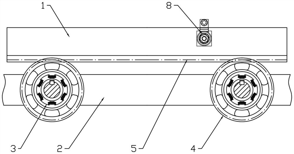
[0022] This embodiment is basically as figure 1 , figure 2 Shown: a material friction noise test bench with a magnetic levitation stage 1, including a stage 1, a stand 2 and four magnetic bearings 3, the magnetic bearing 3 is an active magnetic bearing 3, and the stage 1 is placed on the table Above the frame 2, the magnetic bearing 3 is arranged in parallel, the rotor of the magnetic bearing 3 is pierced with a mounting shaft, the rotor and the mounting shaft are connected by a key, two magnetic bearings 3 are mounted on one mounting shaft, and the two ends of the mounting shaft are fixed on the stand 2, a gear 4 is coaxially fixedly connected to the outer ring of the magnetic bearing 3, the gear 4 is a cylindrical helical gear 4, and two racks 5 are fixedly connected to the bottom surface of the stage 1, and each rack 5 is respectively connected to two Gear 4 meshes.
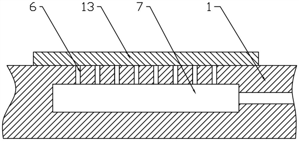
[0023] The central area of ​​the top surface of the stage 1 is provided with a placement area, and the i...

Embodiment 2

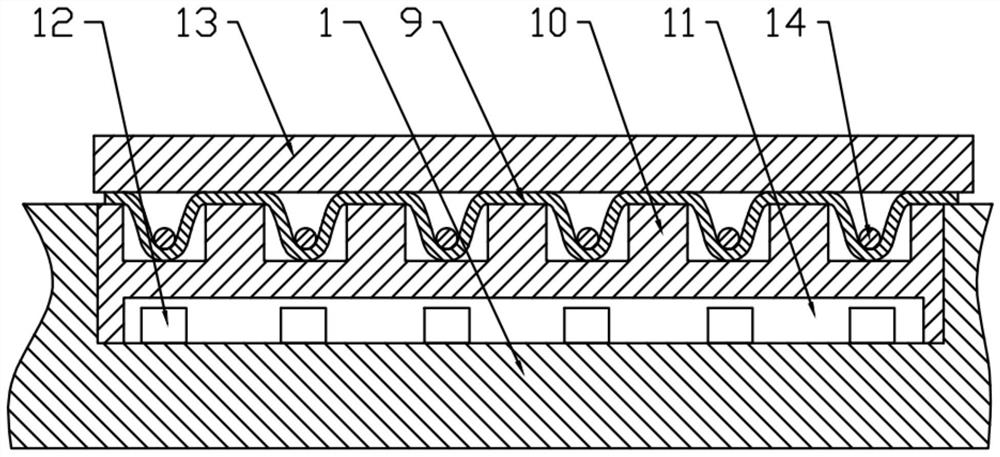
[0028] This embodiment is basically as image 3 As shown, the difference from Embodiment 1 is that: a latex layer 9 made of natural latex is adhered on the top surface of the stage 1 , and nickel-iron alloy particles 14 are embedded inside the latex layer 9 . A nylon backing plate 10 is placed under the latex layer 9, the backing plate 10 is embedded in the object stage 1 and the upper end surface is flush, a cavity 11 is provided in the backing plate 10, and grooves are provided on the cavity 11 corresponding to the positions of the particles 14 , the groove is larger than the particle 14, and an electromagnet 12 is also arranged in the cavity 11.

[0029] After the electromagnet 12 is energized, the particles 14 can be sucked into the groove. Because latex has good elastic deformation capacity, the latex layer 9 is depressed. The effect of the depression is to attach the latex layer 9 to the surface of the test sample 13. Finally, a certain degree of vacuum is generated, wh...


PUM

PropertyMeasurementUnit
depthaaaaaaaaaa

Abstract

The invention belongs to the technical field of friction abnormal sound experiment equipment, and particularly relates to a material friction abnormal sound test with a magnetic levitation type objective table; the test bed comprises an objective table, a rack and at least two magnetic levitation bearings, the objective table is arranged above the rack, the magnetic levitation bearings are arranged in parallel, mounting shafts penetrate through rotors of the magnetic levitation bearings, and the mounting shafts are mounted on the rack. A gear is coaxially and statically connected to an outer ring of the magnetic levitation bearing, and a rack is fixedly connected to the bottom face of the objective table and engaged with the gear. The objective of the invention is to solve the problem that an objective table cannot guarantee a mute effect during a material friction abnormal sound test.

Description

technical field [0001] The invention belongs to the technical field of frictional noise experimental equipment, and in particular relates to a material frictional noise test bench with a magnetic levitation loading platform. Background technique [0002] Car abnormal noise is the sound produced by two materials colliding or rubbing against each other. This sound is almost the most disturbing and unbearable problem for all consumers. The abnormal noise of the vehicle can hardly be completely avoided. Among them, the abnormal noise caused by friction is a common and difficult-to-solve abnormal noise problem in automobiles. The friction coefficient between samples can be tested through the material friction abnormal noise test bench, so that the location where the abnormal noise of the automobile occurs can be determined in the early stage. Predict, eliminate or reduce this sound from the root. [0003] When doing the material friction noise test, the whole process of the mate...

Claims


Application Information

Patent Timeline
Patent Type & Authority Applications(China)
IPC IPC(8): G01N19/02
Inventor 谭成友李沛然佘扬佳饶刚
Owner CHINA AUTOMOTIVE ENG RES INST
Why Eureka
Try Eureka