
Valve facilitating monitoring of water flow velocity

A water flow rate and valve technology, applied to the valve details, valve devices, cocks including cut-off devices, etc., can solve the problems of increased pipeline pressure, difficult scale scraping, pulverized discharge, knowing the water flow rate, etc., to reduce damage The effect of the phenomenon

Pending Publication Date: 2021-04-20
胡天文
View PDF0 Cites 2 Cited by
  • Summary
  • Abstract
  • Description
  • Claims
  • Application Information

AI Technical Summary

Problems solved by technology

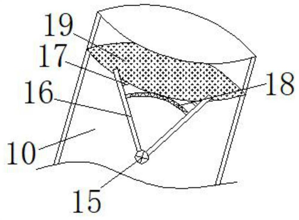
[0004] The purpose of the present invention is to provide a valve that is convenient for monitoring the water flow rate, which solves the problem that when the existing valve is used in the above-mentioned background technology, the water flow power and the monitoring water flow rate are generally provided by electric equipment, so that when the monitoring instrument has a problem, it is difficult to Knowing the water flow rate in time will easily cause the pressure of the water flow on the pipeline to increase and cause damage, and it is not easy to scrape off, pulverize and discharge the scale at the outlet pipe.

Method used


Image

  • Valve facilitating monitoring of water flow velocity
  • Valve facilitating monitoring of water flow velocity
  • Valve facilitating monitoring of water flow velocity

Examples


Embodiment Construction

[0026] The following will clearly and completely describe the technical solutions in the embodiments of the present invention with reference to the accompanying drawings in the embodiments of the present invention. Obviously, the described embodiments are only some, not all, embodiments of the present invention.

[0027] In the description of the present invention, unless otherwise stated, the meaning of "plurality" is two or more; the terms "upper", "lower", "left", "right", "inner", "outer" , "front end", "rear end", "head", "tail", etc. indicate the orientation or positional relationship based on the orientation or positional relationship shown in the drawings, and are only for the convenience of describing the present invention and simplifying the description, rather than Nothing indicating or implying that a referenced device or element must have a particular orientation, be constructed, and operate in a particular orientation should therefore not be construed as limiting ...


PUM


Abstract

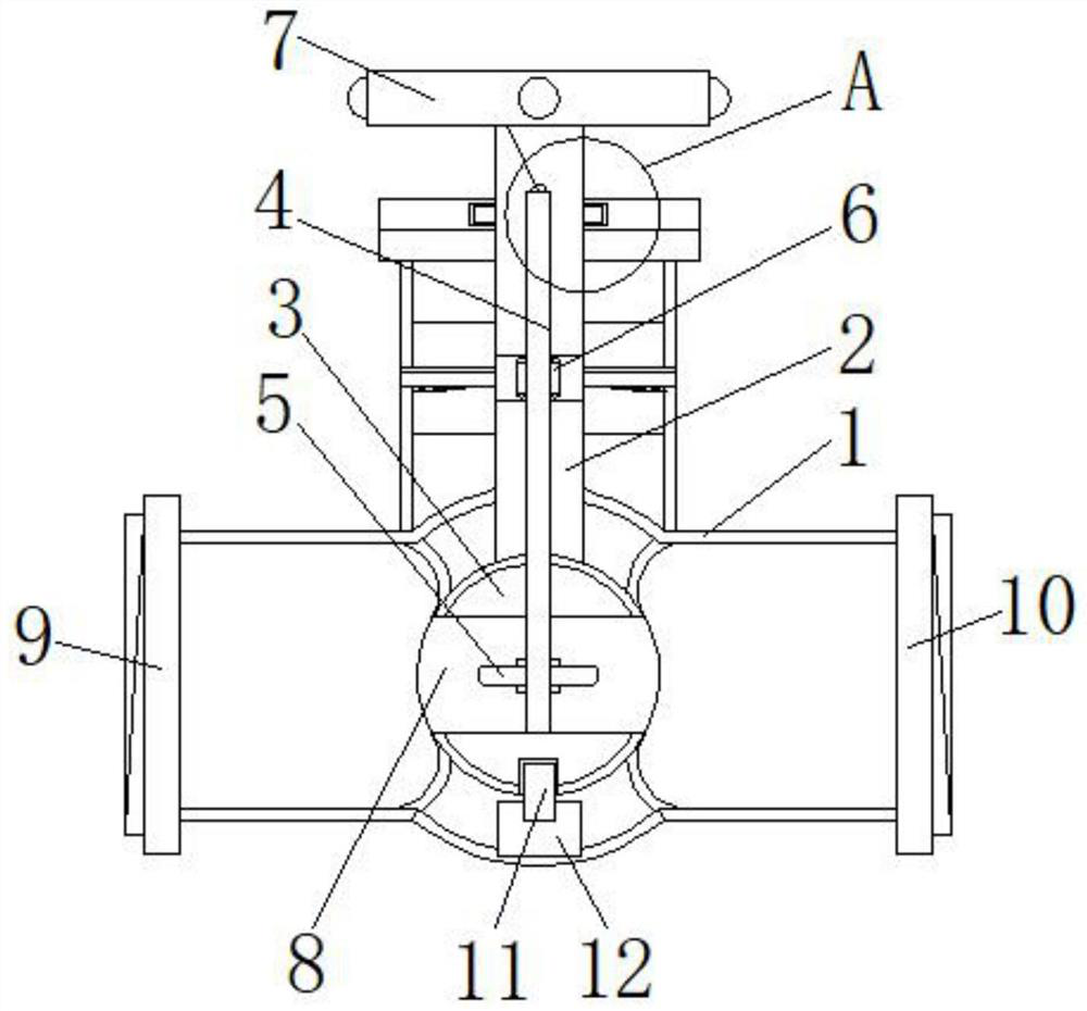
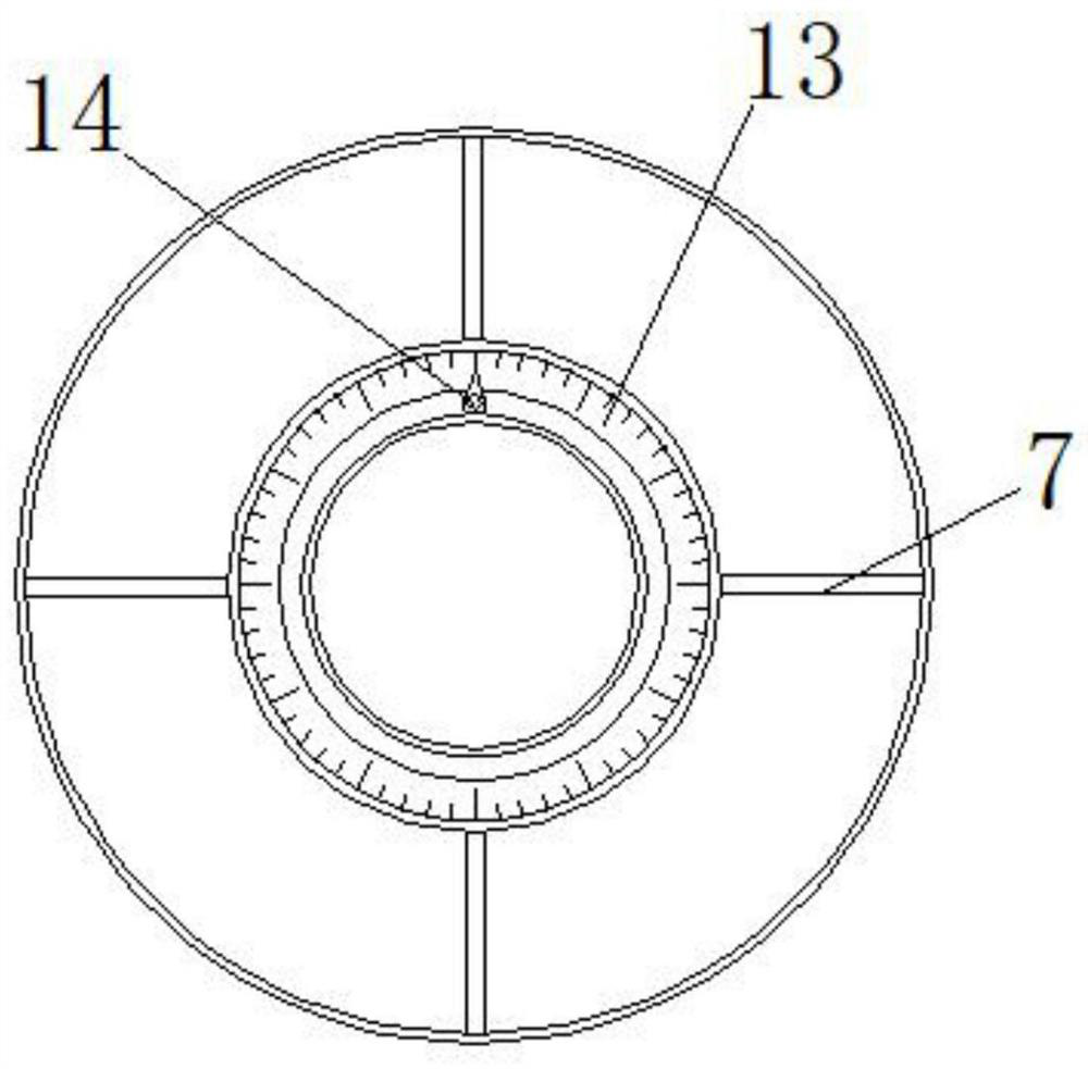
The invention discloses a valve facilitating monitoring of water flow velocity, and relates to the technical field of valves. The valve comprises a valve body, a valve core is arranged on the upper portion of the inner side of the valve body, the bottom end of the valve core is connected with a movable ball, and the movable ball abuts against the inner wall of the valve body; and the inner side of the movable ball is provided with a reserved channel, the bottom end of the movable ball is clamped with a screw rod, and the bottom of the screw rod is in threaded connection with a fixing block. The valve facilitating monitoring of water flow velocity has the beneficial effects that through the arrangement of a movable rod, a support rod, a pull rope, a pointer and a dial disc, after water flow passes through the inner side of the valve, the support rod opposite to the water flow direction is driven to circularly rotate in the water flow direction, and the movable rod connected with the support rod is driven to rotate; and therefore, the pull rope connected to the top end of the movable rod synchronously drives the pointer to rotate along the inner side of a hand wheel, the rotating process of the pointer within the specified time can be known through the dial disc, and the quotient of the process and the time is the water flow velocity.

Description

technical field [0001] The invention relates to the technical field of valves, in particular to a valve convenient for monitoring water flow rate. Background technique [0002] With the development of water conservancy and the progress of the social era, all water conservancy projects require the participation of water flow pipelines, and the equipment that works synchronously with them is indispensable for valves. Therefore, the choice of valves is particularly critical. The cut-off operation can complete the cut-off and delivery of water flow by adjusting the valve at any time. [0003] When the existing valves are in use, they generally provide water flow power and monitor the water flow rate through electric equipment, so that when there is a problem with the monitoring instrument, it is difficult to know the water flow rate in time, which will easily cause the pressure of the water flow on the pipeline to increase, causing damage, and is not easy Disadvantages of opera...

Claims


Application Information

Patent Timeline
Patent Type & Authority Applications(China)
IPC IPC(8): F16K37/00F16K5/06F16K31/60B01D35/04B01D29/01B01D29/03B08B9/043
Inventor 胡天文
Owner 胡天文
Learn More