A printing path planning method, system and 3D printer

A printing path and printing model technology, applied in the field of 3D printing, can solve the problems of one-by-one analysis, accumulation of wasted time, low printing efficiency, etc., to achieve the effect of reducing printing time, shortening the length of space, and ensuring printing accuracy

Active Publication Date: 2022-03-08
TECH & ENG CENT FOR SPACE UTILIZATION CHINESE ACAD OF SCI
View PDF9 Cites 0 Cited by
  • Summary
  • Abstract
  • Description
  • Claims
  • Application Information

AI Technical Summary

Problems solved by technology

[0012] Although the SPSL method traversal can completely splice the entire image, that is, the two-dimensional layered slice image, but because it does not analyze each image, that is, the two-dimensional layered slice image one by one, it is very likely to waste time, that is, the two-dimensional layered slice image The layer slice image is very small, but it still needs to traverse the entire working area, and there is also the problem of empty travel similar to FDM technology
The accumulation of time wasted in the empty travel of each two-dimensional layered slice image will greatly increase the printing time of the entire part, and the printing efficiency is low

Method used

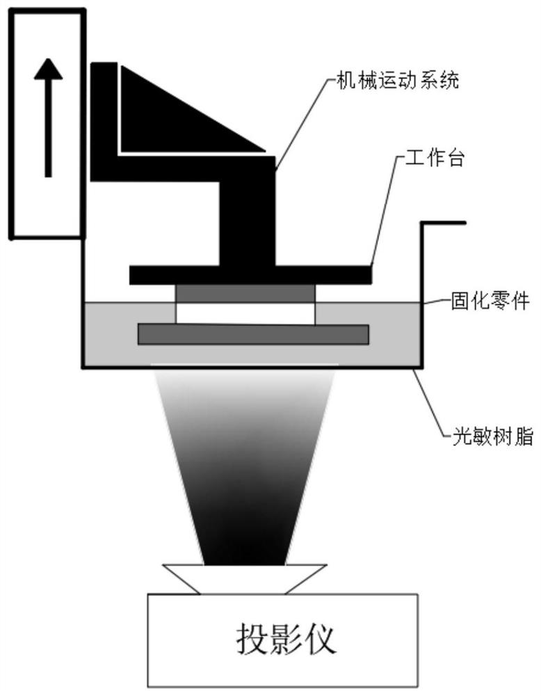
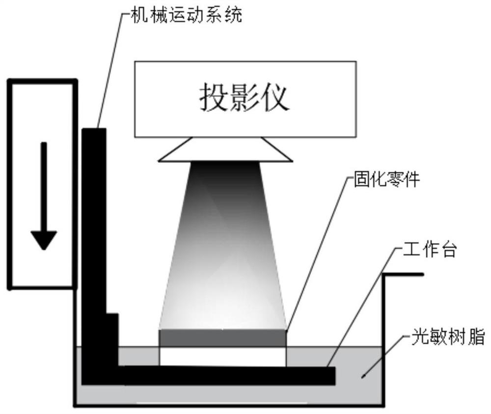
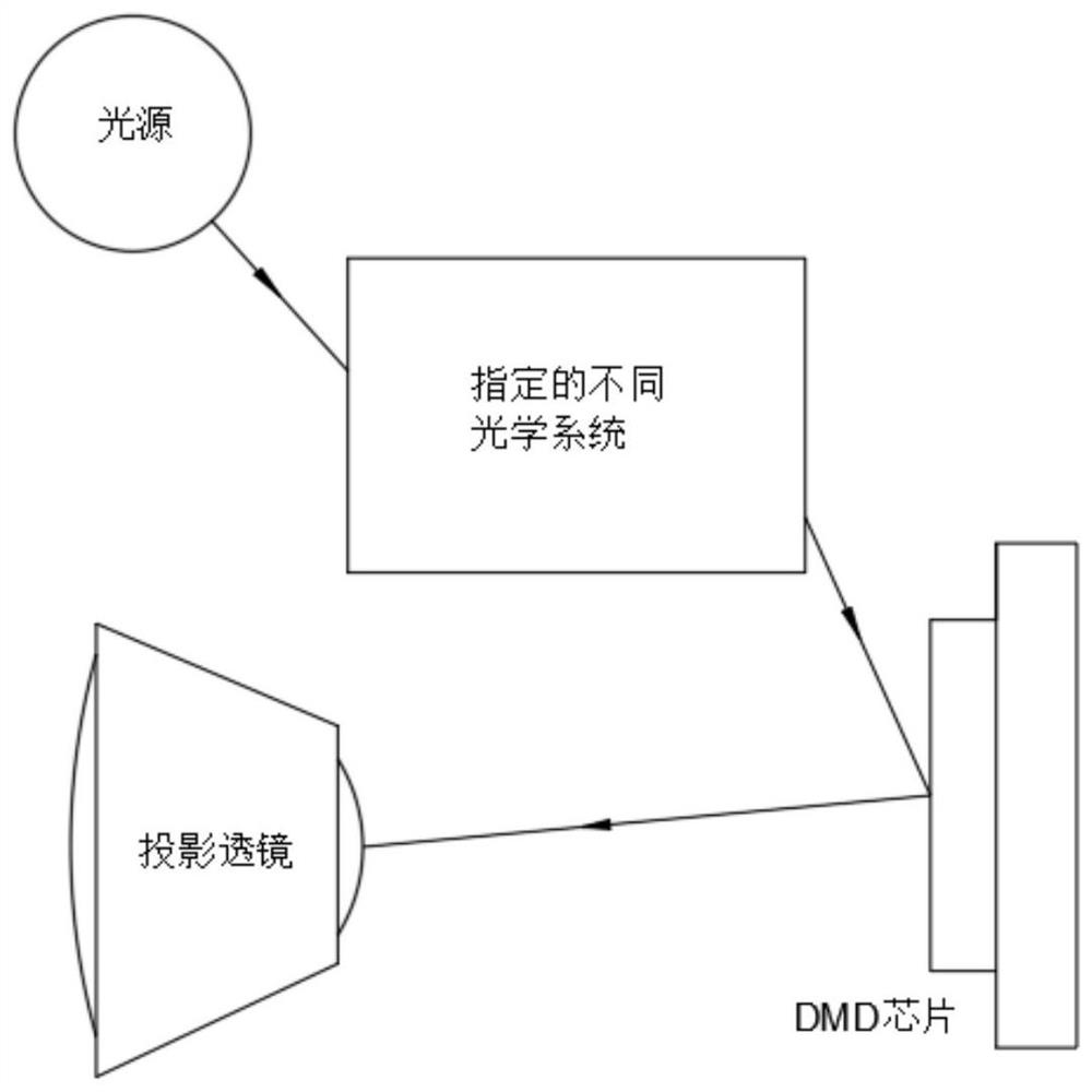

Image

  • A printing path planning method, system and 3D printer
  • A printing path planning method, system and 3D printer
  • A printing path planning method, system and 3D printer

Examples


Embodiment Construction

[0048] Such as figure 1 As shown, a printing path planning method according to an embodiment of the present invention includes the following steps:

[0049] S1. Obtain the shape to be printed according to any two-dimensional layered slice image of the model to be printed;

[0050] S2. Using the optimized improved x-scanning method, and striping the shape to be printed according to preset angle increments, to obtain a plurality of striped rectangles corresponding to each angle;

[0051] S3. Perform partition processing on a plurality of striped rectangles respectively corresponding to each angle by means of z-scanning and based on the optimal distance principle, to obtain the striped rectangles of each partition of each sub-domain corresponding to each angle;

[0052] S4. Obtain the printing path corresponding to the minimum printing time consumption according to the preset algorithm and the striped rectangle of each partition of each subfield corresponding to each angle, and ...


PUM


Abstract

The invention relates to a printing path planning method, system and 3D printer. Firstly, the shape to be printed is divided into strips through an optimized improved x-scanning method to obtain a plurality of striped rectangles corresponding to each angle, and then the z-shaped The method of scanning and based on the principle of optimal distance partitions the multiple striped rectangles corresponding to each angle, and finally, optimizes the striped rectangles of each partition of each sub-domain corresponding to each angle according to the preset algorithm The path can not only ensure the printing accuracy, but also greatly reduce the length of the empty path of the shape to be printed in the two-dimensional layered slice image. Among them, the printing path corresponding to the lowest printing time is selected as the optimal printing path to further reduce Printing time, improve printing efficiency.

Description

technical field [0001] The invention relates to the technical field of 3D printing, in particular to a printing path planning method, system and 3D printer. Background technique [0002] In recent years, rapid prototyping (RP), that is, 3D printing technology, as an additive manufacturing technology, has been widely used in various model production and product testing. Multiple two-dimensional layered slice images are then accumulated and printed layer by layer based on multiple two-dimensional layered slice images to form a solid model. Compared with subtractive manufacturing, it can process products with more complex structures. 3D printing technology has been differentiated after years of development. Many different manufacturing technologies have been developed. Among them, Stereolithography Apparatus (SLA), which uses the principle of photopolymerization of photosensitive resins, was the first to be researched and developed, and has become a relatively mature and widely...

Claims


Application Information

Patent Timeline
Patent Type & Authority Patents(China)
IPC IPC(8): B29C64/393B33Y50/02
Inventor 杨依哲刘兵山李鑫刘晓冬王功
Owner TECH & ENG CENT FOR SPACE UTILIZATION CHINESE ACAD OF SCI
Why Eureka
Try Eureka