Power-driven tool and battery pack
A technology for battery packs and operating machines, which is applied to battery pack components, batteries, electric vehicles, etc., and can solve problems such as battery pack degradation and achieve the effect of suppressing degradation
- Summary
- Abstract
- Description
- Claims
- Application Information
AI Technical Summary
Problems solved by technology
Method used
Image


Examples
no. 1 approach
[0114] Hereinafter, modes for implementing the present disclosure will be described with reference to the drawings.
[0115]
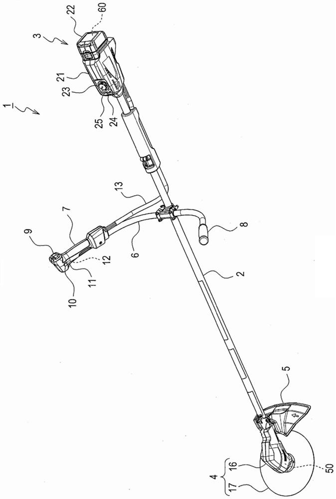
[0116] like figure 1 As shown, in this exemplary embodiment, a case where the electric working machine of the present disclosure is applied to a weeder will be described. The work machine system according to this exemplary embodiment includes a work machine 1 and a battery pack 22 . Work machine 1 is a weeder including a main pipe 2 , a control unit 3 , a drive unit 4 , a cover 5 , and a handle 6 . The main pipe 2 is formed in a long and hollow rod shape. The control unit 3 is provided on the rear end side of the main pipe 2 . The drive unit 4 and the cover 5 are provided on the front end side of the main pipe 2 .
[0117] The drive unit 4 includes a motor case 16 and a cutter 17 . The cutting blade 17 is a disk-shaped blade for cutting objects to be harvested such as grass and small-diameter trees, and is configured to be detachable from the mo...
no. 2 approach
[0221]
[0222] Next, since the basic configuration of the second embodiment is the same as that of the first embodiment, the description of the common configuration will be omitted, and the difference will be mainly described. In addition, the same code|symbol as 1st Embodiment represents the same structure, refer to the above-mentioned description.
[0223]In the first embodiment, when the battery pack 22 is in a state to be protected, two types of discharge prohibition signals are sent from the battery DS terminal 63 and the battery TR terminal 64 to the controller 30 of the work machine 1 . On the other hand, in the second embodiment, when the battery pack 22 is in a state to be protected, three types of discharge prohibition signals are transmitted from the battery DS63 and the battery TR terminal 64 to the controller 30 of the work machine 1, which is different from that of the second embodiment. One embodiment is different. In addition, in the second embodiment, the ...
no. 3 approach
[0260]
[0261] Next, since the basic configuration of the third embodiment is the same as that of the second embodiment, the description of the common configuration will be omitted, and the difference will be mainly described. In addition, the same code|symbol as 2nd Embodiment represents the same structure, refer to the above-mentioned description.
[0262] The output sequence of the three discharge prohibition signals in the third embodiment is different from that in the second embodiment. In addition, in the third embodiment, the battery control circuit 65 and the controller 30 perform half-duplex serial communication with the battery control circuit 65 as an assistant and the controller 30 as the main. The structure of the motor control system 200 of the third embodiment is the same as that of the second embodiment.
[0263]
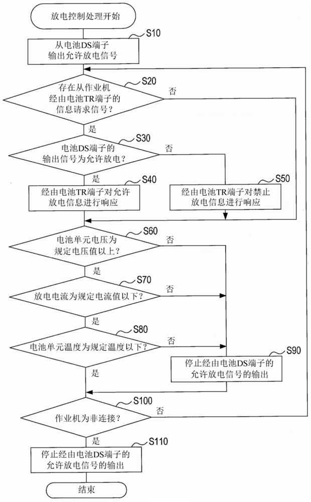
[0264] Next, refer to Figure 12 The flow chart of FIG. 1 illustrates the discharge control process executed by the battery control circuit 6...
PUM
 Abstract
Description
Claims
Application Information
 - R&D
- Intellectual Property
- Life Sciences
- Materials
- Tech Scout
- Unparalleled Data Quality
- Higher Quality Content
- 60% Fewer Hallucinations
Browse by: Latest US Patents, China's latest patents, Technical Efficacy Thesaurus, Application Domain, Technology Topic, Popular Technical Reports.
© 2025 PatSnap. All rights reserved.Legal|Privacy policy|Modern Slavery Act Transparency Statement|Sitemap|About US| Contact US: help@patsnap.com