A resistance heating device and heating method for metal strips
A resistance heating, metal plate and belt technology, applied in electric heating devices, ohmic resistance heating, ohmic resistance heating parts and other directions, can solve the problems of inconvenient picking, time-consuming and laborious, inconvenient heating process, etc., to achieve good heating effect and process. Simple and fast, the heating process is convenient and fast
- Summary
- Abstract
- Description
- Claims
- Application Information
AI Technical Summary
Problems solved by technology
Method used
Image

Examples
Embodiment 1
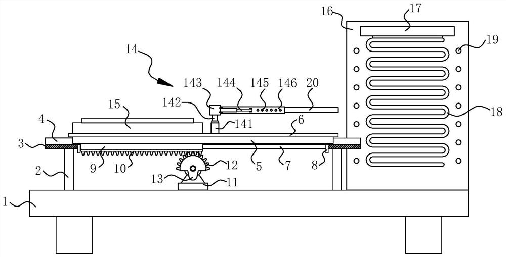
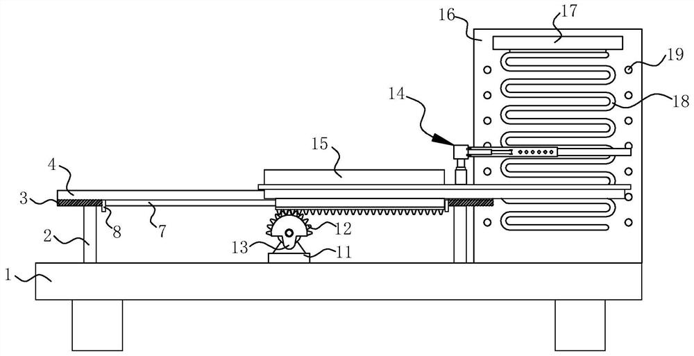
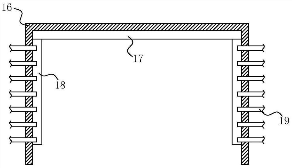
[0028] refer to Figure 1-5 , a resistance heating device for metal strips, comprising a base 1, a box body 16 is fixedly connected to one side of the upper surface of the base 1, a heating device 17 is fixedly connected to the inner top of the box body 16, and two heating devices are fixedly connected to the heating device 17. Two resistance heating wires 18, and two resistance heating wires 18 are all fixedly connected on both sides of the inner wall of box body 16 respectively, and the both sides of box body 16 inner walls are respectively fixed and communicated with several blowing pipes 19 uniformly, and heating device 17 is electric The heater, the heating device 17 is connected with the external power supply device through the wire, and the switch that controls the operation of the heating device 17 is fixedly connected on the wire, and the heating device 17 is started to make the resistance heating wire 18 generate heat, so that the metal plate can be heated. Heating f...
Embodiment 2
[0031] refer to Figure 5 , as another preferred embodiment of the present invention, the difference from Embodiment 1 is that the sliding mechanism includes a slider 22 and a chute 23, the slider 22 is fixedly connected to one side of the lower surface of the connecting plate 6, and the chute 23 is opened On one side of the upper surface of the fixed plate 3, and the slider 22 is slidably arranged in the chute 23, the chute 23 is a dovetail groove, the slider 22 is a dovetail structure, and the slider 22 and the chute 23 are mutually compatible. Matching, through the setting of the slider 22 and the chute 23, the stability of the connecting plate 6 and the metal plate during the moving process can be guaranteed.
Embodiment 3
[0033] refer to figure 1 , figure 2 and Figure 4As another preferred embodiment of the present invention, the difference from Embodiment 1 is that the pick-up mechanism 14 includes an electric telescopic rod 141, and the electric telescopic rod 141 is fixedly connected on the connecting plate 6, and the upper end of the electric telescopic rod 141 is fixedly connected with a The first motor 142, one end of the output shaft of the first motor 142 is fixedly connected with a connection block 143, and the two ends of the connection block 143 near the box body 16 side are respectively hinged with electric push rods 144, and between the two electric push rods 144 For relative arrangement, one side of the connection block 143 is hinged with two splints 146 respectively, and the opposite sides of the two splints 146 are respectively hinged with one end of the two electric push rods 144, and the metal plate 20 is clamped on the two splints 146. Between, the opposite sides of the t...
PUM
 Abstract
Description
Claims
Application Information
 - Generate Ideas
- Intellectual Property
- Life Sciences
- Materials
- Tech Scout
- Unparalleled Data Quality
- Higher Quality Content
- 60% Fewer Hallucinations
Browse by: Latest US Patents, China's latest patents, Technical Efficacy Thesaurus, Application Domain, Technology Topic, Popular Technical Reports.
© 2025 PatSnap. All rights reserved.Legal|Privacy policy|Modern Slavery Act Transparency Statement|Sitemap|About US| Contact US: help@patsnap.com