
Scribing device for ship plate beveling stage in shipbuilding

A scribing device and beveling technology, which is applied in the field of scribing devices in the beveling stage of ship construction, can solve problems such as affecting the construction period of sections, exceeding the accuracy, and affecting the section accuracy of the main dimensions of the panel. , to reduce the possibility of replacing the plate, improve the construction accuracy, and achieve the effect of simple structure

Inactive Publication Date: 2021-04-16
HUDONG ZHONGHUA SHIPBUILDINGGROUP
View PDF8 Cites 0 Cited by
  • Summary
  • Abstract
  • Description
  • Claims
  • Application Information

AI Technical Summary

Problems solved by technology

[0004] Welding groove processing, some welding methods require parts to be grooved on the edge of the plate, and some cutting machines can directly cut out welding grooves. For parts cut by cutting machines that cannot cut grooves, the general welding groove processing method Usually, there are two kinds of mechanical edge planing (milling) method and flame cutting method. At present, the flame cutting method is used more often in welding grooves in general shipyards. The main reason is the high efficiency; , if the welding groove processing quality does not meet the accuracy requirements, it will affect the subsequent process, and if it is serious, the plate will be replaced, which will affect the segmental construction cycle
At present, the general K-type, Y-type, and X-type welding grooves will be set to leave roots, and the construction personnel on site need to mark the root places before processing such welding grooves before processing. If the scribing accuracy is poor, it will directly lead to the out-of-tolerance phenomenon in the groove processing. In the large panel stage, it is necessary to carry out too much turn over carbon planing, which will affect the main size of the panel and the subsequent segmentation accuracy.

Method used


Image

  • Scribing device for ship plate beveling stage in shipbuilding
  • Scribing device for ship plate beveling stage in shipbuilding
  • Scribing device for ship plate beveling stage in shipbuilding

Examples


Embodiment Construction

[0020] In order to better understand the technical solutions of the present invention, the embodiments of the present invention will be described in detail below in conjunction with the accompanying drawings.

[0021] It should be clear that the described embodiments are only some of the embodiments of the present invention, not all of them. Based on the embodiments of the present invention, all other embodiments obtained by persons of ordinary skill in the art without creative efforts fall within the protection scope of the present invention.

[0022] The present application will be described in further detail below through specific embodiments and in conjunction with the accompanying drawings.

[0023] In describing the present invention, it should be understood that the terms "longitudinal", "transverse", "upper", "lower", "front", "rear", "left", "right", "vertical", The orientation or positional relationship indicated by "horizontal", "top", "bottom", "inner", "outer", e...


PUM


Abstract

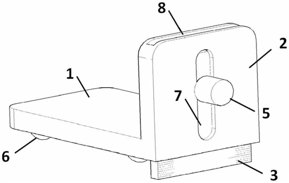
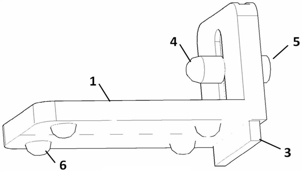
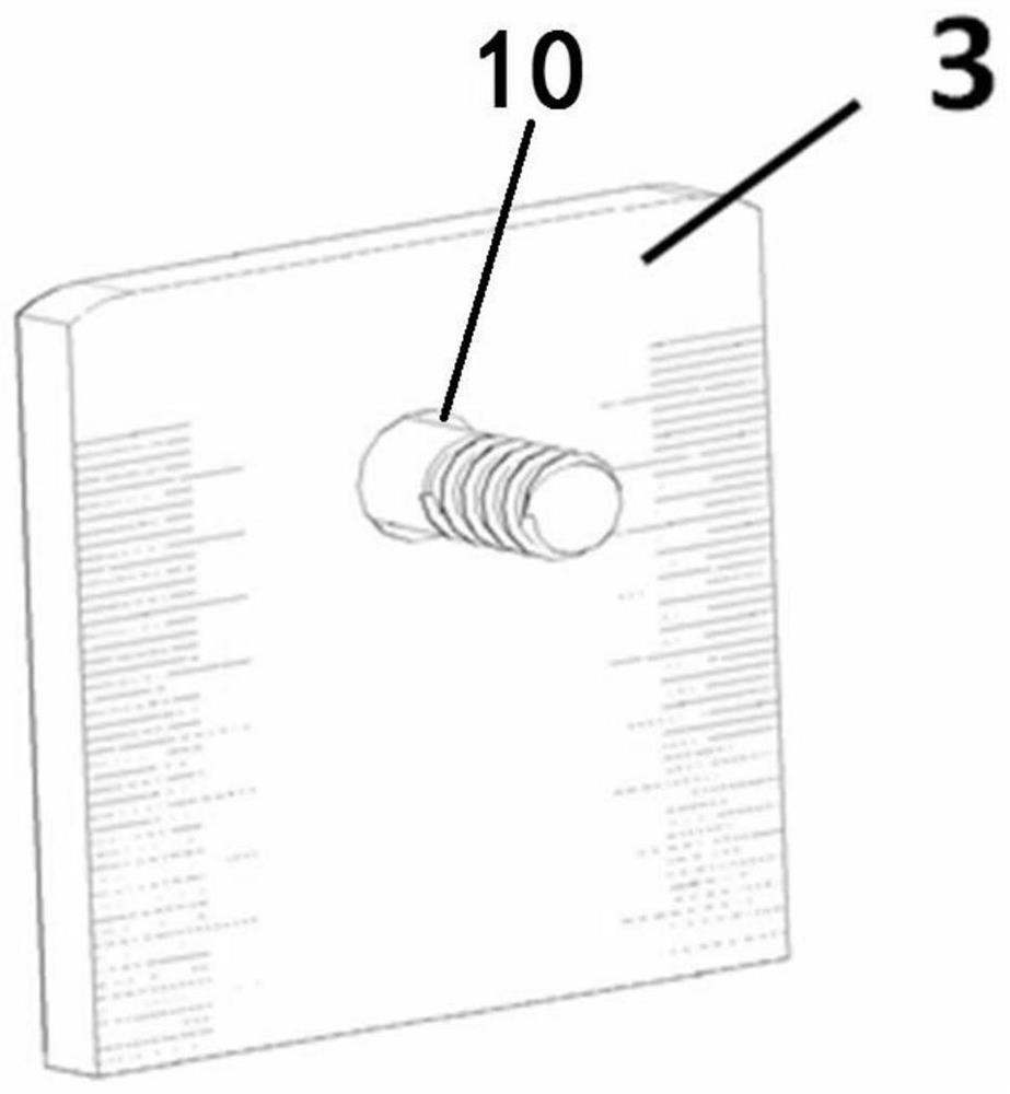
The invention discloses a scribing device for a ship plate beveling stage in shipbuilding, comprising a sliding plate and a baffle plate perpendicularly fixed to the side edge of the sliding plate, wherein a hollowed-out groove penetrating from the top to the bottom is formed in the baffle plate, a sliding scale plate is embedded into the hollowed-out groove, a clamping groove is longitudinally formed in the end surface of the baffle plate; and the sliding scale plate is locked and fixed through a fastener penetrating through the clamping groove. The scribing device can be used for scribing the edge machining welding groove in shipbuilding, can guarantee the accuracy of the scribing position at the root of the welding groove, can effectively guarantee the machining precision of the welding groove, avoids a phenomenon that the welding groove is machined mistakenly due to factors such as work errors of operators or inaccurate scribing on a construction site, reduces the possibility of subsequent plate replacement, and effectively improves the construction precision of plate splicing and segmentation.

Description

[0001] This patent is a divisional application of the invention patent application 202010363793.9 on April 30, 2020 technical field [0002] The invention relates to the technical field of shipbuilding, in particular to a marking device used in the beveling stage of shipboards in shipbuilding. Background technique [0003] In the shipbuilding process, the processing of hull components can be divided into edge processing and forming processing of hull components. Edge processing mainly refers to the cutting and separation of hull steel materials that have been nested and the processing of welding grooves. The edge processing methods mainly include mechanical cutting. cutting method (shearing, punching, planing, milling), chemical cutting method (gas cutting) and physical cutting method (plasma cutting and laser cutting, etc.). [0004] Welding groove processing, some welding methods require parts to be grooved on the edge of the plate, and some cutting machines can directly c...

Claims


Application Information

Patent Timeline
Patent Type & Authority Applications(China)
IPC IPC(8): B25H7/04
CPCB25H7/045
Inventor 陈诚鲁德智吉李祥程海涛
Owner HUDONG ZHONGHUA SHIPBUILDINGGROUP
Learn More