
Metal rod fixed-length cutting device for manufacturing alloy milling cutter

A cutting device and metal rod technology, applied in positioning devices, feeding devices, metal processing and other directions, can solve problems such as low work efficiency, waste splashing, safety threats to workers, etc., to improve work efficiency, avoid waste splashing, Easy to clean effect

Inactive Publication Date: 2021-04-16
邵阳县国安工具有限公司
View PDF0 Cites 1 Cited by
  • Summary
  • Abstract
  • Description
  • Claims
  • Application Information

AI Technical Summary

Problems solved by technology

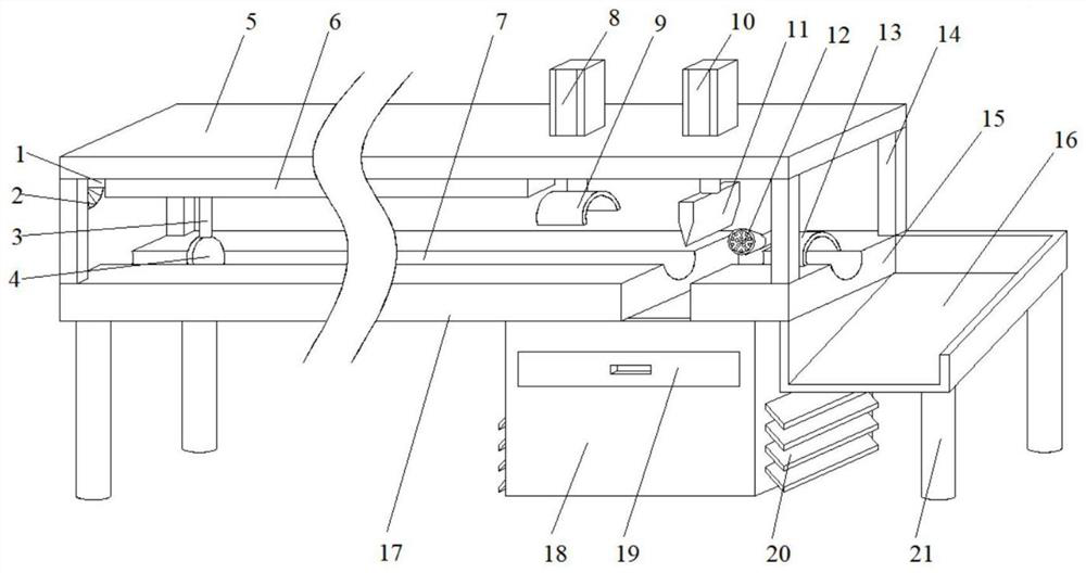
[0003] The existing metal rod cutting device for making alloy milling cutters cannot perform automatic fixed-length cutting, and it is necessary to manually measure the moving length and then fix it at the bottom of the cutter for cutting, which is inefficient; the existing metal rod for making alloy milling cutters The rod cutting device is easy to cause the waste generated by cutting to splash, which not only poses a threat to the safety of the staff, but also takes time and effort for manual collection and cleaning

Method used


Image

  • Metal rod fixed-length cutting device for manufacturing alloy milling cutter
  • Metal rod fixed-length cutting device for manufacturing alloy milling cutter
  • Metal rod fixed-length cutting device for manufacturing alloy milling cutter

Examples


Embodiment Construction

[0027] The following will clearly and completely describe the technical solutions in the embodiments of the present invention with reference to the accompanying drawings in the embodiments of the present invention. Obviously, the described embodiments are only some, not all, embodiments of the present invention.

[0028] In describing the present invention, it should be understood that the terms "upper", "lower", "front", "rear", "left", "right", "top", "bottom", "inner", " The orientation or positional relationship indicated by "outside", etc. is based on the orientation or positional relationship shown in the drawings, and is only for the convenience of describing the present invention and simplifying the description, rather than indicating or implying that the referred device or element must have a specific orientation, so as to Specific orientation configurations and operations, therefore, are not to be construed as limitations on the invention.

[0029] refer to Figure ...


PUM


Abstract

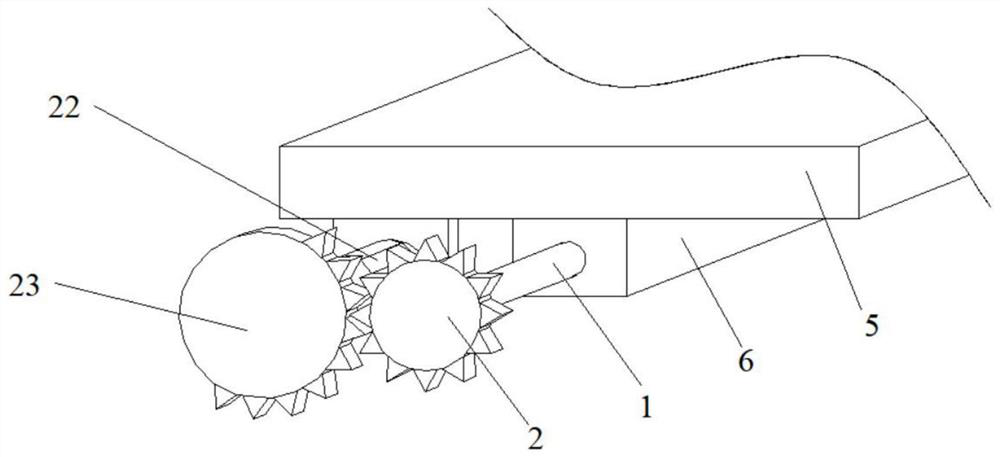
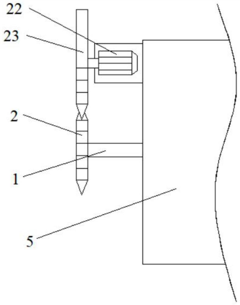
The invention belongs to the technical field of milling cutter manufacturing, particularly relates to a metal rod fixed-length cutting device for alloy milling cutter manufacturing, and provides the following scheme for solving the problem that fixed-length cutting cannot be achieved: the metal rod fixed-length cutting device comprises a workbench, a bearing table and a top plate; a mounting box is horizontally welded to the middle of the bottom of the top plate; the middle of the mounting box is horizontally and rotatably connected with a lead screw; one end of the lead screw extends out of the mounting box and is provided with a driven gear; a forward and reverse motor is horizontally mounted at one corner of one side of the top plate; a driving gear is mounted at the top end of an output shaft of the forward and reverse motor; a push disc is slidably connected into a placing groove in the top of the workbench; a moving mechanism for driving the push disc to move is arranged in the mounting box; and a discharging table is welded to the other side of the bearing table; and a water tank is installed at the bottom between the workbench and the bearing table. Fixed-length cutting can be carried out on a metal rod, the working efficiency is improved, manual discharging is not needed, time and labor are saved, and sweeps are prevented from splashing.

Description

technical field [0001] The invention relates to the technical field of making milling cutters, in particular to a metal rod fixed-length cutting device for making alloy milling cutters. Background technique [0002] Milling cutter is used for milling. It has one or more cutter teeth. When working, each cutter tooth cuts off the allowance of workpiece intermittently. Milling cutter is mainly used to process planes, steps and grooves on milling machines. , forming surfaces and cutting workpieces, etc. Alloy milling cutter is a milling cutter made of alloy material. The metal rod is an important part of the alloy milling cutter. Because the length of the metal rod of the alloy milling cutter of the same specification is the same, it is necessary to cut the metal rod to a fixed length. [0003] The existing metal rod cutting device for making alloy milling cutters cannot perform automatic fixed-length cutting, and it is necessary to manually measure the moving length and then f...

Claims


Application Information

Patent Timeline
IPC IPC(8): B23D79/00B23Q3/06B23Q5/26B23Q7/00B23Q11/00B23Q11/10B01D29/03B01D35/02B01D36/04B03C1/02
Inventor 谢良桂
Owner 邵阳县国安工具有限公司
Learn More