
Gap waveguide antenna structure and electronic equipment

A technology of antenna structure and gap waveguide, which is applied in the direction of antenna grounding switch structure connection, waveguide, antenna, etc., can solve problems such as energy loss and reduce energy transmission efficiency, and achieve the effects of reduced energy loss, better integration, and reduced loss

Active Publication Date: 2021-04-13
HUAWEI TECH CO LTD
View PDF7 Cites 2 Cited by
  • Summary
  • Abstract
  • Description
  • Claims
  • Application Information

AI Technical Summary

Problems solved by technology

[0004] In the common gap waveguide slot antenna structure, the energy transmission between the microstrip line and the gap waveguide adopts the coupling feeding method, and the microstrip line is directly laid on the upper surface of the printed circuit board (PCB). The coupling between the line and the gap waveguide, but because there is a PCB dielectric layer between the top layer of the gap waveguide and the pin periodic structure, the PCB dielectric layer causes a large degree of energy loss during the energy transmission process, which reduces the energy transmission efficiency.

Method used


Image

  • Gap waveguide antenna structure and electronic equipment
  • Gap waveguide antenna structure and electronic equipment
  • Gap waveguide antenna structure and electronic equipment

Examples


Embodiment Construction

[0042] The technical solutions in the embodiments of the present application will be described below with reference to the drawings in the embodiments of the present application.

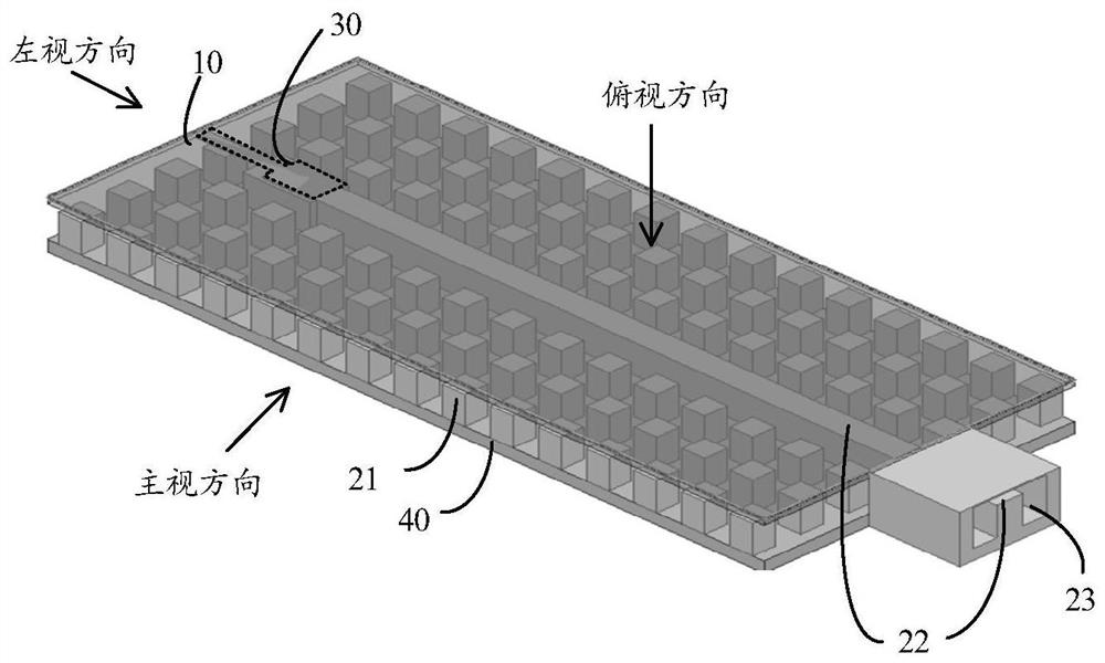
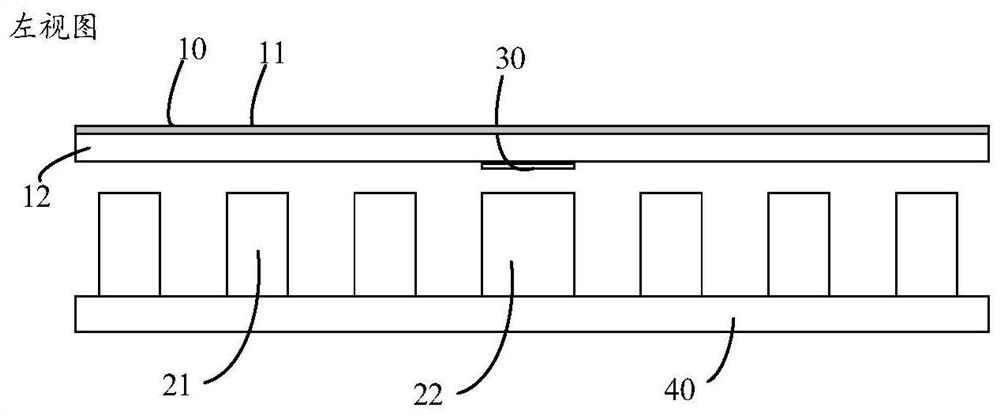
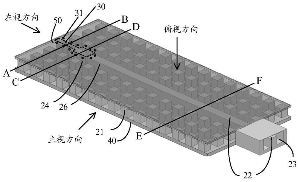
[0043] figure 1 is a schematic diagram of a gapped waveguide antenna structure. Such as figure 1 As shown, the gap waveguide antenna structure includes a top layer 10 , a gap waveguide structure 20 , a microstrip structure 30 and a bottom layer 40 .

[0044] The top layer 10 includes a metal layer, and the metal layer serves as the ground of the PCB board. The top layer 10 also includes a PCB dielectric layer, and the metal layer is laid on the upper surface of the PCB dielectric layer.

[0045] The gap waveguide structure 20 includes a pin periodic structure 21 and a ridge structure 22, which are arranged on the upper surface of the bottom layer 40 and form a gap with the top layer 10. Specifically, the upper surface of the pin periodic structure 21 and the ridge structure 22 are in contact with ...


PUM


Abstract

The invention provides a gap waveguide antenna structure and electronic equipment, and relates to the field of communication radars. The antenna structure comprises a top layer, a gap waveguide structure, a microstrip structure and a bottom layer, the top layer is parallel to the bottom layer, and a first metal layer and a second metal layer are respectively laid at two sides of a dielectric layer of the top layer. The microstrip structure is arranged in the second metal layer, and the frame of the microstrip structure is separated from the metal of the second metal layer through a gap. The above special antenna structure can reduce the transmission loss, improve the coupling capability, and effectively improve the transmission efficiency of energy or electromagnetic waves. Besides, a component or a chip and the like can be arranged on the second metal layer, so that the integration of the antenna structure is improved, and the application range of the antenna structure is expanded.

Description

technical field [0001] The present application relates to the field of communication radar, and more specifically, to a gap waveguide antenna structure and electronic equipment. Background technique [0002] With the continuous development of high-frequency technology and millimeter wave technology, low-loss planar antennas have been well applied. Traditional waveguide slot antennas are a good choice for high frequency applications. However, generally speaking, the feeding network of the waveguide slot antenna is very complicated, and its processing accuracy is difficult to guarantee. Compared with the traditional waveguide slot antenna, the gap waveguide structure greatly reduces the difficulty of processing and assembly, which promotes the application of the waveguide slot antenna in the millimeter wave field. [0003] In the millimeter wave frequency band, the integrated design of the antenna and the active radio frequency circuit based on monolithic microwave integrate...

Claims


Application Information

Patent Timeline
Patent Type & Authority Applications(China)
IPC IPC(8): H01Q1/50H01Q1/00H01Q1/36H01P3/18
CPCH01Q1/50H01Q1/002H01Q1/36H01P3/18H01P3/081H01P5/107H01Q9/0407H01Q13/206
Inventor 赵志东李强劳大鹏杨勇
Owner HUAWEI TECH CO LTD
Learn More