
Narrow-band frequency hopping radio signal identification method

A radio signal and identification method technology, applied in the direction of electrical components, interference to communication, transmission system, etc., can solve the problems of easy masquerading as legitimate signals and loss of frequency hopping security, so as to prevent masquerading as legitimate signals and improve security sexual effect

Inactive Publication Date: 2021-04-13
MARELLI AUTOMOBILE ELECTRONIS GUANGZHOU CO LTD
View PDF7 Cites 0 Cited by
  • Summary
  • Abstract
  • Description
  • Claims
  • Application Information

AI Technical Summary

Problems solved by technology

For civil communications, because the frequency range allowed by the regulations is limited, an illegal transmitter can send a radio signal covering the entire allowed frequency range, so that the receiver can be tuned to any frequency within the allowed frequency range. Every point can receive the illegal signal, so that it can pretend to be a legal transmitter without knowing the predetermined frequency hopping frequency sequence, and the existing frequency hopping receiver can always receive the signal from the transmitter according to the predetermined frequency sequence signal, the communication process loses the security brought by frequency hopping, such as the wireless communication between the car and the remote control key, if frequency hopping communication is used, it can increase the difficulty and cost of relay attacks, but for existing The receiving method of the transmitter, if the illegal transmitter replaces the frequency hopping transmitter by covering the entire frequency band allowed by the regulations, it is easy to masquerade as a legitimate signal

Method used


Image

  • Narrow-band frequency hopping radio signal identification method

Examples


Embodiment Construction

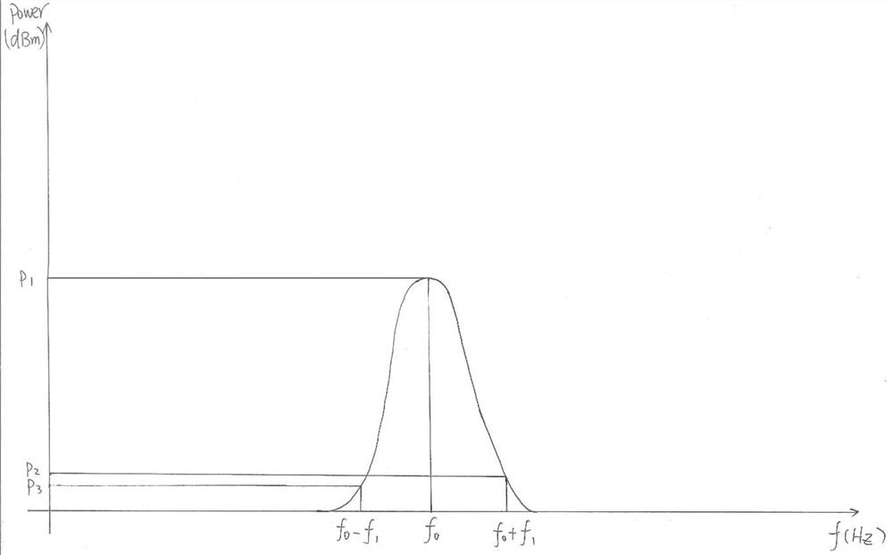
[0010] Such as figure 1 As shown, a narrowband frequency hopping radio signal identification method comprises the following steps:

[0011] By simultaneously or within short time intervals of a predetermined frequency (f 0 ) and adjacent frequencies on both sides (f 0 -f 1 , f 0 +f 1 ) radio signal for detection and demodulation;

[0012] Comparing the power corresponding to the predetermined frequency of the narrowband frequency hopping radio signal and the radio signals of adjacent frequencies on both sides;

[0013] When the power corresponding to the radio signals of adjacent frequencies on both sides is less than the first threshold value of the power corresponding to the predetermined frequency of the narrowband frequency hopping radio signal, and the power difference corresponding to the radio signals of adjacent frequencies on both sides is less than the second threshold value, it is judged that the The radio signal is a legal narrowband frequency hopping signal,...


PUM


Abstract

The invention discloses a narrow-band frequency hopping radio signal identification method, which comprises the following steps: simultaneously or within a short time interval, detecting and demodulating radio signals of a predetermined frequency of a narrow-band frequency hopping radio signal and adjacent frequencies on two sides of the narrow-band frequency hopping radio signal; comparing the preset frequency of the narrow-band frequency hopping radio signal with the power corresponding to the radio signals with the adjacent frequencies on the two sides of the narrow-band frequency hopping radio signal; and when the power corresponding to the radio signals with the adjacent frequencies on the two sides is smaller than a first threshold value of the power corresponding to the preset frequency of the narrow-band frequency hopping radio signal, and the power difference corresponding to the radio signals with the adjacent frequencies on the two sides is smaller than a second threshold value, judging that the narrow-band frequency hopping radio signal is a legal signal, otherwise, judging that the narrow-band frequency hopping radio signal is an illegal signal. The method can effectively distinguish whether a signal to be received is a frequency hopping radio signal sent by a legal transmitter according to a preset frequency or a fixed frequency radio signal covering the whole frequency band and sent by an illegal transmitter. The application of frequency hopping radio communication with increased security can be extended to the field of narrow-band wireless communication.

Description

technical field [0001] The invention relates to the technical field of narrowband frequency hopping radio signal identification, in particular to a narrowband frequency hopping radio signal identification method. Background technique [0002] The transmitter of frequency hopping communication in the prior art performs information modulation (first modulation) on the carrier signal and second modulation on the modulated carrier (frequency modulation according to a predetermined frequency sequence), and the receiver follows the same Frequency sequence to tune reception. For civil communications, because the frequency range allowed by the regulations is limited, an illegal transmitter can send a radio signal covering the entire allowed frequency range, so that the receiver can be tuned to any frequency within the allowed frequency range. Every point can receive the illegal signal, so that it can pretend to be a legal transmitter without knowing the predetermined frequency hopp...

Claims


Application Information

Patent Timeline
Patent Type & Authority Applications(China)
IPC IPC(8): H04B1/713H04K3/00H04B1/715
CPCH04B1/713H04B1/715H04K3/22
Inventor 李晓华
Owner MARELLI AUTOMOBILE ELECTRONIS GUANGZHOU CO LTD
Learn More