Flanged cylindrical battery with spiral wound electrode

A cylindrical battery and spiral winding technology, which is applied in the direction of non-aqueous electrolyte batteries, lithium batteries, secondary batteries, etc., can solve the problems of low working efficiency of the battery pack, inability to ventilate and dissipate the battery pack, and achieve the effect of ensuring the cooling effect

Pending Publication Date: 2021-04-13
SHENZHEN BEIZEER ELECTRONICS CO LTD
View PDF0 Cites 0 Cited by
  • Summary
  • Abstract
  • Description
  • Claims
  • Application Information

AI Technical Summary

Problems solved by technology

[0004] Based on the existing flanged cylindrical battery with spirally wound electrodes, when the existing cylindrical battery forms a battery pack, due to the filling of electrolyte, it cannot effectively ventilate and dissipate the battery pack, resulting in low working efficiency of the battery pack technical problem, the present invention proposes a flanged cylindrical battery with spirally wound electrodes

Method used


Image

  • Flanged cylindrical battery with spiral wound electrode
  • Flanged cylindrical battery with spiral wound electrode
  • Flanged cylindrical battery with spiral wound electrode

Examples


Embodiment 1

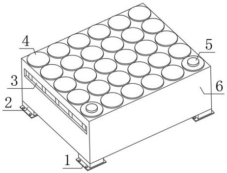
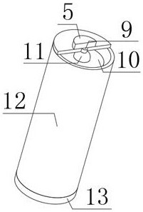
[0030] refer to Figure 1-5 , a flanged cylindrical battery with spirally wound electrodes, including a fixing frame 6, the top outer wall of the fixing frame 6 is provided with placement grooves 7 distributed equidistantly, and the bottom inner wall of the placement groove 7 is provided with installation wire grooves 8, A fixed base 13 is provided on the inner wall of the bottom of the placement groove 7, and a groove is arranged on the outer wall of the top of the fixed base 13, and the groove is set to a structure with a narrow top and a wide bottom, and the bottom inner wall of the groove is provided with through holes 15 distributed in a spiral manner. , a winding unit is provided on the inner wall of the bottom of the groove, and an integrated line is provided on one side of the outer wall of the winding unit, a filling layer 19 is provided inside the integrated line, and an air electrode 16, a first The positive electrode separator 17, the first negative electrode separ...

Embodiment 2

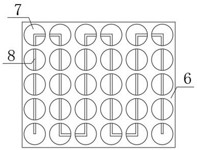
[0039] refer to Image 6 , a flanged cylindrical battery with spirally wound electrodes, including a fixing frame 6, the top outer wall of the fixing frame 6 is provided with placement grooves 7 distributed equidistantly, and the bottom inner wall of the placement groove 7 is provided with installation wire grooves 8, A fixed base 13 is provided on the inner wall of the bottom of the placement groove 7, and a groove is arranged on the outer wall of the top of the fixed base 13, and the groove is set to a structure with a narrow top and a wide bottom, and the bottom inner wall of the groove is provided with through holes 15 distributed in a spiral manner. , a winding unit is provided on the inner wall of the bottom of the groove, and an integrated line is provided on one side of the outer wall of the winding unit, a filling layer 19 is provided inside the integrated line, and an air electrode 16, a first The positive electrode separator 17, the first negative electrode separato...


PUM


Abstract

The invention discloses a flanged cylindrical battery with a spiral wound electrode, and aims to solve the problem that the working efficiency of a battery pack is relatively low because the battery pack cannot be effectively ventilated and cooled due to the filling of electrolyte when the battery pack is formed by a conventional cylindrical battery, and the flanged cylindrical battery comprises a fixing frame, placing grooves distributed at equal intervals are formed in the outer wall of the top of the fixing frame, mounting wire grooves are formed in the inner walls of the bottoms of the placing grooves, fixing bases are arranged on the inner walls of the bottoms of the placing grooves, grooves are formed in the outer walls of the tops of the fixing bases, and the grooves are arranged to be of a structure with the narrow upper portion and the wide lower portion. The grooves are arranged to be of the structure with the narrow upper portion and the wide lower portion, the electrolyte is loaded in the grooves, the electrolyte cannot be spilled out even if the battery pack shakes to a certain degree, in this way, air holes can be reasonably formed in the outer walls of the two sides of the fixing frame, and the heat dissipation effect of the battery pack in the fixing frame is effectively guaranteed.

Description

technical field [0001] The invention relates to the technical field of cylindrical batteries, in particular to a flanged cylindrical battery with spirally wound electrodes. Background technique [0002] At present, the cylindrical battery is a battery with high capacity, long cycle life and wide operating environment temperature. Products are used in solar lamps, lawn lamps, backup energy, power tools, toy models, and photovoltaic energy. It is divided into different systems of lithium iron phosphate, lithium cobaltate, lithium manganate, cobalt-manganese mixture, and ternary materials. The shell is divided into two types: steel shell and polymer. Different material systems have different advantages. Mainly steel-cased cylindrical lithium iron phosphate batteries. Iron-lithium batteries are characterized by high capacity, high output voltage, good charge-discharge cycle performance, stable output voltage, high-current discharge, electrochemical stability, and safety in use ...

Claims


Application Information

Patent Timeline
Patent Type & Authority Applications(China)
IPC IPC(8): H01M50/242H01M50/213H01M50/244H01M50/682H01M10/613H01M10/643H01M10/6556H01M10/6561H01M10/052
CPCH01M10/052H01M10/613H01M10/643H01M10/6556H01M10/6561Y02E60/10
Inventor 曹振武方建军朱亚
Owner SHENZHEN BEIZEER ELECTRONICS CO LTD
Why Eureka
Try Eureka