Cylindrical rotary body wall thickness detection method
A detection method and a technology of a rotating body, applied in the direction of mechanical thickness measurement, measuring devices, mechanical measuring devices, etc., can solve the problems of high friction and wear of detection tools, low efficiency, and high labor intensity of workers, so as to achieve stable light spots and reduce wear Effect
Active Publication Date: 2021-04-13
ZHONGBEI UNIV
View PDF6 Cites 0 Cited by
- Summary
- Abstract
- Description
- Claims
- Application Information
AI Technical Summary
Problems solved by technology
[0003]
The purpose of the present invention: to overcome the problems of insufficient detection accuracy of existing detection methods, large friction and wear of detection tools, low efficiency, and high labor intensity of workers
Method used
View moreImage
Smart ImageViewing Examples
Examples
specific Embodiment approach
[0022] Specific implementation of the probe head: the probe head does not have air holes, and the probe head directly contacts the hole wall; the probe head has air holes, and the probe head does not directly contact the hole wall.
Embodiment approach
[0023] Fulcrum implementation mode: use a ball pair or a ball joint or other methods.
Login to View More PUM
 Abstract
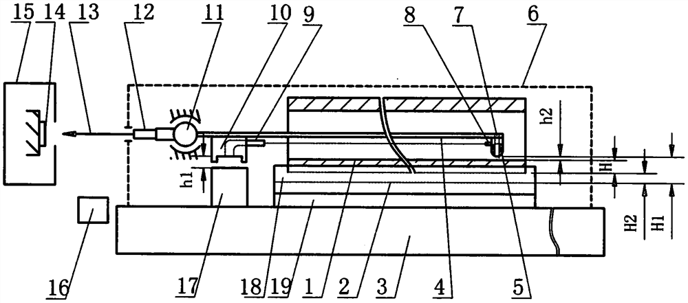
The invention belongs to the field of machining and detection, and particularly relates to a cylindrical rotary body wall thickness detection method. A cylindrical rotary body is placed on a V-shaped block of equipment used in the detection method and moves along a guide rail. A detection head is in contact with the hole wall, or an air film is arranged between the detection head and the hole wall. When the wall thickness changes, a detection rod, the detection head and the light spot change accordingly, and the wall thickness is obtained through the operation display. The detection method comprises the following steps of: 1, measuring the relationship among the light spot position, H and h2 by using a group of cylindrical revolved bodies with known wall thickness; 2, placing the cylindrical rotary body to be detected, and starting an air source and a light source; and 3, acquiring the wall thickness or a mean value and a variance of the cylindrical rotary body by a computer. When the detection head is separated from the hole wall by the air film, the frictional wear is small; and the detection result is slightly influenced by the surface roughness of the inner hole. The equipment has the effect of error amplification, can reduce the adverse effect of relative rotation of an optical part on a detection result, and is higher in detection precision and efficiency.
Description
technical field [0001] The invention belongs to the field of mechanical processing and detection, and in particular relates to a method for detecting the wall thickness of a cylindrical rotating body. Background technique [0002] At present, mechanical tools such as dial gauges, dial gauges, and lever dial gauges are generally used to measure the wall thickness of cylindrical rotary bodies. Most of the existing detection methods are contact measurement, and the detection tools have a large friction coefficient, serious wear and short service life. The existing detection method has low precision and low degree of automation, relying on manual reading, which is prone to human error and low detection efficiency. Contents of the invention [0003] The purpose of the present invention is to overcome the problems of insufficient detection accuracy, high friction and wear of detection tools, low efficiency and high labor intensity of existing detection methods. [0004] The pr...
Claims
Login to View More Application Information
Patent Timeline
 Patent Type & Authority Applications(China)
IPC IPC(8): G01B11/06G01B5/06G01B11/00G01B5/004G01B5/00
CPCG01B11/06G01B5/06G01B5/0002G01B11/002G01B5/004
Inventor 刘瑶
Owner ZHONGBEI UNIV
- R&D Engineer
- R&D Manager
- IP Professional
- Industry Leading Data Capabilities
- Powerful AI technology
- Patent DNA Extraction
Learn More Browse by: Latest US Patents, China's latest patents, Technical Efficacy Thesaurus, Application Domain, Technology Topic, Popular Technical Reports.
© 2024 PatSnap. All rights reserved.Legal|Privacy policy|Modern Slavery Act Transparency Statement|Sitemap|About US| Contact US: help@patsnap.com


