
Damping rotating body and damper

A technology of rotating body and damper, which is applied in the direction of liquid shock absorber, shock absorber, shock absorber, etc., can solve the problem of increasing the inventory of damping rotating body, identifying and managing the number of production molds, increasing the production cost of damper, and reducing shell The oil storage capacity of the body cavity and other issues can be improved to improve the rotation stability and precision, improve the service life and reduce the installation steps.

Pending Publication Date: 2021-04-13
GANZHOU HEYING AUTO PARTS
View PDF0 Cites 1 Cited by
  • Summary
  • Abstract
  • Description
  • Claims
  • Application Information

AI Technical Summary

Problems solved by technology

[0002] The existing clockwise damper and counterclockwise damper have roughly the same structure, the only difference is that the direction of the combined structural characteristics of the damping rotating body and the central rotating shaft is different, and the damper needs different damping rotating bodies when switching between forward and reverse directions. The inventory of the damping rotating body, the number of production molds, the production time, and the identification and management costs of two different damping rotating bodies are increased, which increases the production cost of the damper; and when the existing one-way damper is assembled, due to damping rotation The upper surface of the body is closed, and the grease in the damper casing rushes out from the outer edge of the damping rotating body and splashes out of the edge of the casing, which reduces the oil storage capacity of the casing cavity, reduces the resistance value of the damper, and affects The damping performance of the damper

Method used


Image

  • Damping rotating body and damper
  • Damping rotating body and damper
  • Damping rotating body and damper

Examples


Embodiment 1

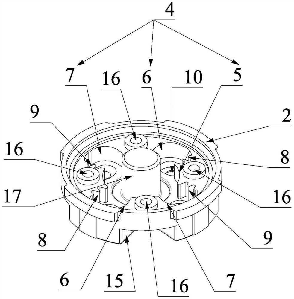
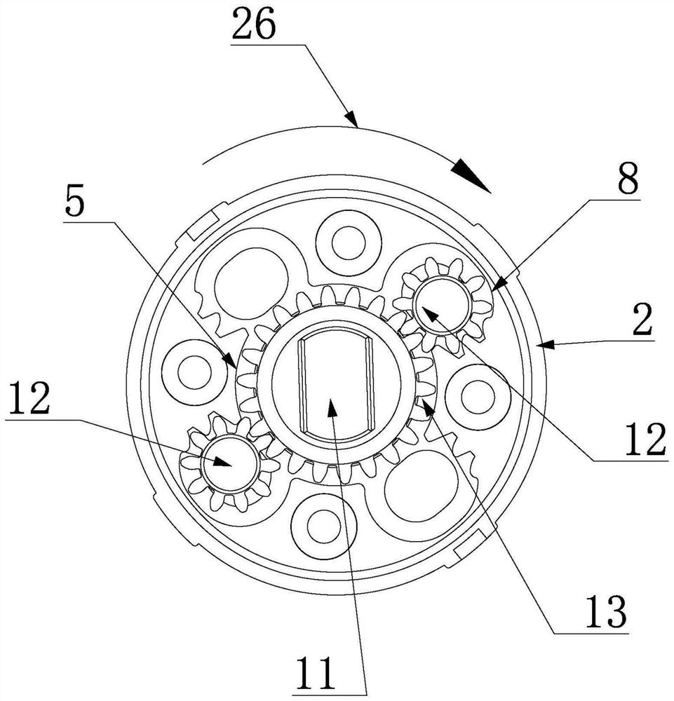
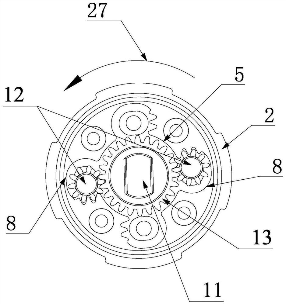
[0035]This embodiment provides a damping rotating body 1, such asFigure 1 ~ 4As shown in this embodiment, the damping rotating body 1 includes a rotating body 2 and a slot cover 3, and the rotating body 2 is used to arrange a gear rendrone on one side surface of the rotary body 2. 4, the gear rendering groove 4 includes a positioning a circle slot 5, a plurality of clockwise arc grooves 6 and a plurality of counterclockwise arc grooves 7, clockwise arc grooves 6, and counterclockwise grooves 7 can preferably be a long arc. The grooves, each clockwise arc groove 6 and each counterclockwise arc groove 7 each can accommodate a card-contact gear 12, and the positioning round groove 5 can accommodate the drive gear 13 that meshes with each of the respective cartridge gear 12, the card connection The gear 12 can rotate the axis of the drive gear 13 in the drive gear 13 or counterclockwise under the drive of the drive gear 13, and each clockwise arc-shaped groove 6 is clockwise clockwise w...

Embodiment 2

[0042]This embodiment provides a damper 25, such asFigure 1 ~ 4As shown in this embodiment, the damper 25 includes a damper housing 19, a housing cover 20, and a damper rotating body 1 in the first embodiment, the housing cover 20 closed the damper housing 19, the housing cover 20 and The damper housing 19 forms the accommodating chamber 21, and the damping rotating body 1 is disposed within the accommodating chamber 21, and a number of clockwise arcuate grooves 6 and several counterclockwise arc grooves 7 are provided on the rotating body 2, each of the various times. The first gear groove 8 capable of engaging the engagement gear 12 is provided on the side wall surface of the engaging gear 12, and each counterclockwise arc-shaped groove 7 is provided on the side wall surface opposite the axis of the positioning round groove 5 axle. Both the side wall surface of the groove 5 axis counterclockwise is provided with the arrangement of the second gear groove 9 that can be engaged with ...


PUM


Abstract

The invention discloses a damping rotating body, and relates to the technical field of dampers. The damping rotating body comprises a rotating main body and a groove cover, and first gear grooves capable of being engaged with clamping gears are formed in the side wall faces, opposite to the clockwise direction around the axis of a positioning circular groove, of all clockwise arc-shaped grooves; second gear grooves capable of being engaged with the clamping gears are formed in the side wall surface, opposite to the anticlockwise direction around the axis of the positioning circular groove, of all anticlockwise arc-shaped grooves; first oil passing holes communicating gear containing grooves with the interior of a damper shell are formed in the rotating main body; and second oil passing holes communicating the gear containing grooves with the interior of the damper shell are formed in the groove cover. The invention further discloses a damper. The damper comprises a damper shell, a shell cover and the damping rotating body; the shell cover seals the damper shell; the shell cover and the damper shell form a containing cavity; the damping rotating body is arranged in the containing cavity; and the production cost can be reduced, and the damping performance of the damper is improved.

Description

Technical field[0001]The present invention relates to the field of damper, and more particularly to a damping rotating body and a damper.Background technique[0002]The existing clockwise damper and counterclockwise damper structure are substantially the same, and the difference is that the damper is not the same as the binding structure of the center shaft, and the damper requires different damping rotates when switching from each other when switching from each other. Increase the inventory of the damping rotating body, the number of molds, and the production time and the identification management cost of two different damping rotators, improve the production cost of the damper; and the existing one-way damper is assembled, due to damping rotation The upper surface of the body is closed, and the oil in the damper housing is rolled out from the outer edge of the damper rotating body, and the housing type cavity reservoir is reducing the amount of the damper, which reduces the resistan...

Claims


Application Information

Patent Timeline
Patent Type & Authority Applications(China)
IPC IPC(8): F16F9/12F16F9/32
CPCF16F9/12F16F9/3207
Inventor 王盛
Owner GANZHOU HEYING AUTO PARTS
Learn More