
An electromagnetic holding type tin wiping device

An electromagnetic device, holding technology, applied in glass transportation equipment, manufacturing tools, glass manufacturing equipment, etc., can solve the problems of difficulty in controlling the amount of counterweights, lack of elastic parts in the tin wiping device, and poor airtightness. It is convenient to find problems and eliminate them in time, save labor and time costs, and avoid the effect of unqualified glass

Active Publication Date: 2022-03-25
BENGBU TRIUMPH ENG TECH CO LTD
View PDF7 Cites 0 Cited by
  • Summary
  • Abstract
  • Description
  • Claims
  • Application Information

AI Technical Summary

Problems solved by technology

However, these two structures have certain shortcomings in the actual application process, which is not easy to use.
The first structure is to use the principle of leverage to adjust the height by increasing the counterweight. The leaf spring provides a certain buffer force to ensure good contact between the graphite and the roller surface. Disadvantages: the elasticity of the leaf spring will gradually fail and need to be replaced frequently; the counterweight It is difficult to control how much graphite is added. If more graphite blocks are in hard contact with the roller surface, it will cause vibration. If less graphite is added, the effect of rubbing tin is not good.
In the second structure, the gas spring itself has two states, one is the initial state, and the other is the extended state. The gas spring is controlled to switch between the two states by turning on and off the gas to achieve the function of lifting the graphite block. Disadvantages: its stroke It is fixed and cannot be adjusted. The graphite block may not touch the roller surface or the graphite block presses the roller surface on site. The gas spring is difficult to replace, and the airtightness is not good, and air leakage often occurs
[0006] Moreover, due to the design form of the leaf spring and gas spring, the operator cannot observe the working condition of the tin wiping device at any time. If there is tin slag remaining on the roller surface due to the failure of the leaf spring or gas spring at this time, it will cause scratches on the glass. In this case, only when the original glass quality inspection equipment hundreds of meters away from the sealed box reflects that there is a problem with the quality of the glass, the operator will go to find the place and cause of the problem. During this period, a lot of manpower must be spent and time cost, and the glass during this period is unqualified, which will cause huge losses to the enterprise
[0007] The comparative document with the publication number CN203346281U discloses an adjustable fixed-point tin wiping device. Specifically, pull the handle of the pull rod backwards, and then tighten the fixing nut at the rear after pulling to the required strength, so that it can be wiped and tinned by itself. The device lacks elastic parts, the tin wiping is stiff, and it is easy to damage the surface to be wiped, and the mechanical structure is used to link the tin wiping device, which is cumbersome to operate and complicated in structure

Method used


Image

  • An electromagnetic holding type tin wiping device
  • An electromagnetic holding type tin wiping device
  • An electromagnetic holding type tin wiping device

Examples


Embodiment Construction

[0030] In order to facilitate those skilled in the art to understand the technical solution of the present invention, the technical solution of the present invention will be further described in conjunction with the accompanying drawings.

[0031]The terms "first" and "second" are used for descriptive purposes only, and cannot be understood as indicating or implying relative importance or implicitly specifying the quantity of indicated technical features. Thus, a feature defined as "first" and "second" may explicitly or implicitly include one or more of these features. In the description of the present application, "plurality" means two or more, unless otherwise specifically defined.

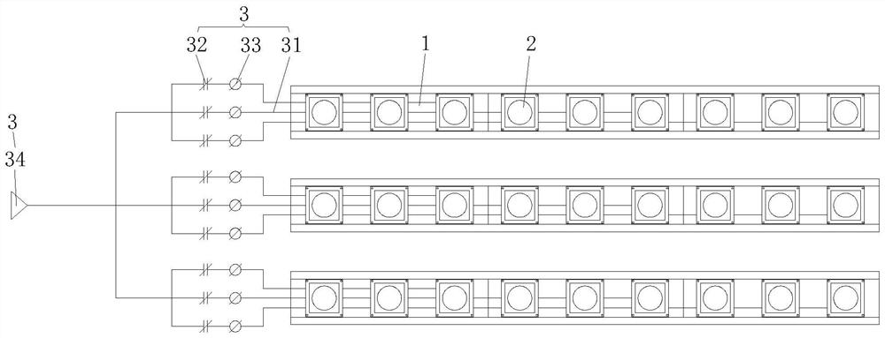
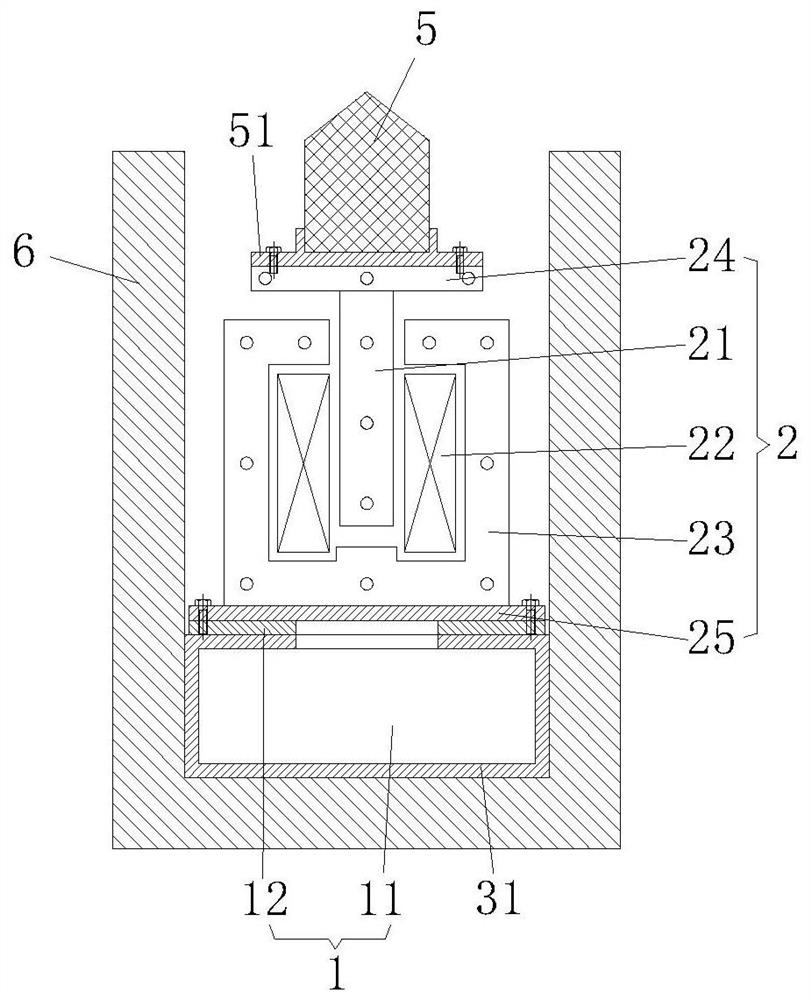
[0032] refer to figure 1 , This embodiment discloses an electromagnetic holding type tin wiping device, including a wire routing device 1 , an electromagnetic device 2 , an electric control component 3 , a transition roller 4 , graphite 5 and an electromagnetic shell 6 .

[0033] refer to fig...


PUM


Abstract

The invention discloses an electromagnetic holding type tin wiping device, which comprises an electromagnetic device, an electric control component, a transition roller and graphite for wiping tin on the surface of the transition roller; the electromagnetic device includes a magnetic rod and an electromagnetic coil; the magnetic rod Set in the magnetic field after the electromagnetic coil is energized; and when changing the magnetic force of the electromagnetic coil, the magnetic bar moves along the direction perpendicular to the transition roller; the top of the magnetic bar is fixedly connected with the graphite; the graphite is subjected to electromagnetic force when the magnetic bar Under the action, it is pasted on the roller surface of the transition roller; the electric control component includes a wire and a power supply; the power supply is electrically connected to the electromagnetic coil through a wire; a regulator for adjusting the current of the circuit is installed on the wire, and the present invention , by setting the regulator to change the size of the circuit current, and then change the magnetic force of the electromagnetic coil to adjust the height of the magnetic rod, so that the graphite on the magnetic rod fits on the surface of the transition roller for tin wiping, which is easy to adjust and has a good tin wiping effect.

Description

technical field [0001] The invention relates to the technical field of glass mechanical tin wiping, in particular to an electromagnetic holding type tin wiping device. Background technique [0002] Float glass is named after molten glass floating on the surface of molten tin. Since this production method does not need to overcome the gravity of the glass itself, the width of the original glass plate can be increased, the pulling speed can be greatly increased, and the output and production scale can be increased; Polished high-quality mirror, its surface flatness and parallelism can be compared with mechanical polished glass, and its mechanical properties and chemical stability are better than mechanical polished glass, so float glass has been popularized quickly since its birth. [0003] The annealing process of float glass is an important step to determine the quality of float glass. It means that after the molten glass is formed in the tin bath, the thermal stress genera...

Claims


Application Information

Patent Timeline
Patent Type & Authority Patents(China)
IPC IPC(8): C03B35/16C03B18/02
CPCC03B35/168C03B35/166C03B18/02
Inventor 徐星葛军张兴孙建国成冲刘雨虹张德三许彬
Owner BENGBU TRIUMPH ENG TECH CO LTD
Learn More