Intelligent tracking industrial robot base

An industrial robot and intelligent tracking technology, which is applied to manipulators, manufacturing tools, program-controlled manipulators, etc., can solve problems such as inability to intelligently track and cannot match different types of industrial robots, and achieve flexible and adaptable base devices strong effect

Pending Publication Date: 2021-04-13
ANHUI TECHN COLLEGE OF MECHANICAL & ELECTRICAL ENG
View PDF7 Cites 0 Cited by
  • Summary
  • Abstract
  • Description
  • Claims
  • Application Information

AI Technical Summary

Problems solved by technology

[0005] Therefore, the technical problem to be solved by the present invention is to overcome the defects in the prior art that cannot intelligently track and cannot match different types of industrial robots, thereby providing an intelligent tracking industrial robot base

Method used


Image

  • Intelligent tracking industrial robot base
  • Intelligent tracking industrial robot base
  • Intelligent tracking industrial robot base

Examples


Embodiment 1

[0024] This embodiment provides a base for an intelligent tracking industrial robot, such as Figure 1-3 shown, including

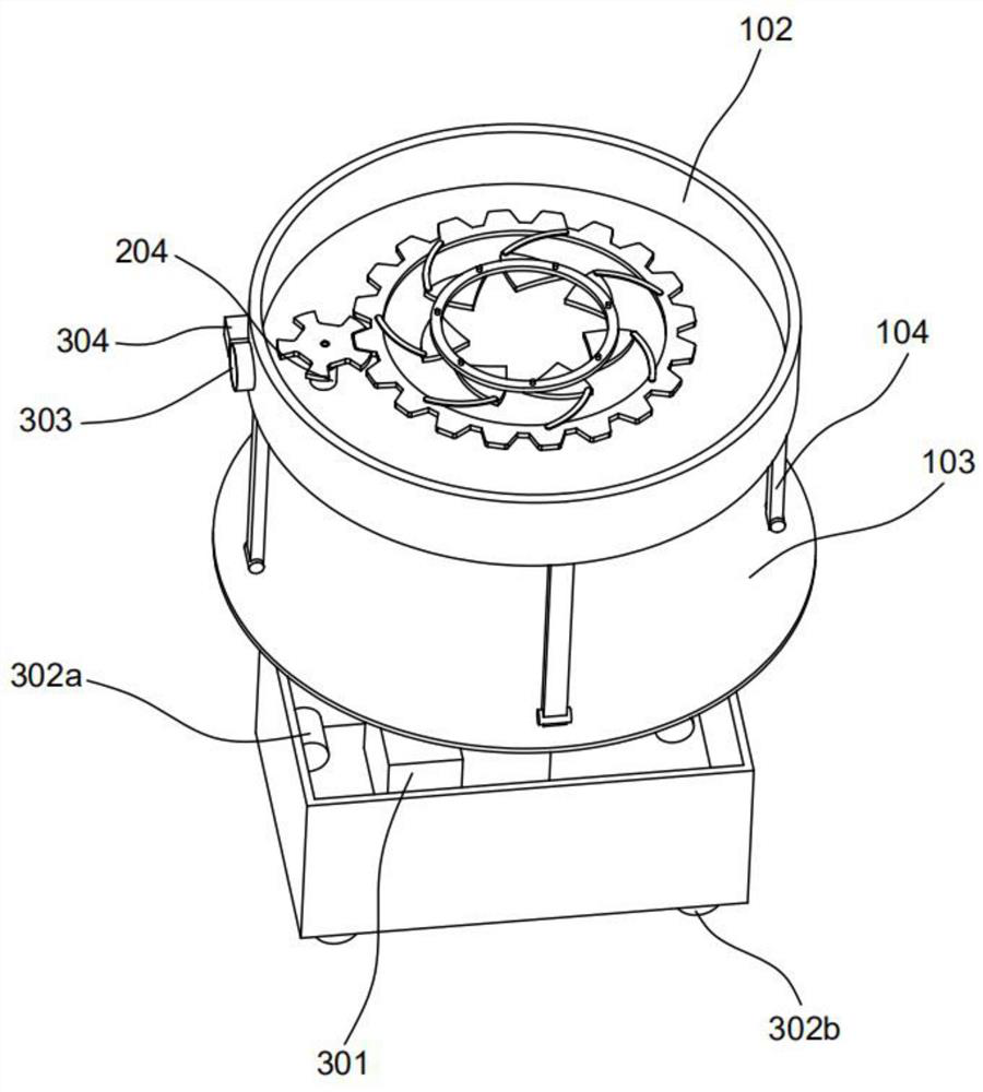
[0025] The outer casing 100 includes a lower casing 101 and an upper casing 102 arranged above the lower casing 101; Unit 202 ; and tracking module 300 , which includes a control unit 301 and a drive unit 302 arranged in the lower casing 101 , and also includes a camera 303 and an ultrasonic pan-tilt 304 arranged at the front end of the upper casing 102 .

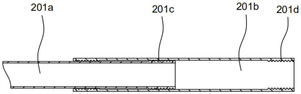
[0026] A tray 103 is arranged above the lower casing 101, and the telescopic unit 201 includes a connecting rod 201a arranged between the lower casing 101 and the tray 103. A sleeve 201b is sleeved on the outside of the connecting rod 201a, and the connecting rod 201a is slidably connected to the sleeve 201b. ; The end of the connecting rod 201a close to the sleeve 201b is circumferentially provided with an external thread 201c, and the inner side of the sleeve 201b is provided with a corresponding in...

Embodiment 2

[0031] This embodiment is different from the previous embodiment in that, as Figure 1-3 as shown,

[0032] The drive unit 302 includes a drive motor 302a arranged in the lower housing 101, and the outside of the drive motor 302a is connected with a wheel 302b; both sides of the front end of the lower housing 101 are also provided with obstacle avoidance modules 305; the control unit 301, the drive unit 302, the camera 303, An electrical connection is adopted between the ultrasonic pan-tilt 304 and the obstacle avoidance module 305 .

[0033]The control unit 301 includes a processor 301a; the processor 301a adopts an ATMEGA328p chip, which can perform high-speed calculations on the collected signals, and has high internal integration precision, which can completely omit traditional complex circuits, and has dynamic power consumption inside the chip. function, which allows the device to achieve a current consumption as low as 238μA in the running mode. The chip has a large-cap...


PUM


Abstract

The invention provides an intelligent tracking industrial robot base. The robot base comprises an outer shell, an adjusting module and a tracking module, wherein the outer shell comprises a lower shell and an upper shell located above the lower shell. The adjusting module comprises a telescopic unit arranged above the lower shell and further comprises a clamping unit arranged in the upper shell; the tracking module comprises a control unit and a driving unit which are arranged in the lower shell, and further comprises a camera and an ultrasonic cradle head which are arranged at the front end of the upper shell; through the telescopic unit, lifting of the base can be controlled, and the height of an industrial robot is adjusted; through the clamping unit, the intelligent tracking industrial robot base is suitable for industrial robots of different sizes, the adaptability of the robot base is higher, multiple states can be adjusted at the same time, and the base device is more flexible and changeable; and the base can automatically walk to find a way through the tracking module, and manual control is not needed.

Description

technical field [0001] The invention relates to the technical field of industrial robots, in particular to an intelligent tracking industrial robot base. Background technique [0002] Industrial robots are multi-joint manipulators or robots with multiple degrees of freedom for the industrial field. An industrial robot is a machine device that performs work automatically, and is a machine that realizes various functions by its own power and control capabilities. It can accept human command, and can also run in accordance with pre-programmed programs. Modern industrial robots can also act according to the principles and guidelines formulated by artificial intelligence technology. Because industrial robots need to be used in a wide range of places, they often appear in many places. In the case of local use, the base of the industrial robot is very important, so an industrial robot connection base is needed. [0003] However, the existing industrial robot connection base still...

Claims


Application Information

Patent Timeline
IPC IPC(8): B25J9/16B25J19/02B25J19/00
CPCB25J9/1676B25J9/1679B25J9/1697B25J19/00B25J19/023
Inventor 杨浩王宇
Owner ANHUI TECHN COLLEGE OF MECHANICAL & ELECTRICAL ENG
Why Eureka
Try Eureka