
Variable transmission mechanism of electric motorcycles

A technology of speed change mechanism and electric scooter, applied in the direction of electric vehicle, motor, electric components, etc.

Inactive Publication Date: 2021-04-09
吴健铭 +2
View PDF6 Cites 0 Cited by
  • Summary
  • Abstract
  • Description
  • Claims
  • Application Information

AI Technical Summary

Problems solved by technology

[0006] In order to solve the problems existing in the prior art, the present invention provides a speed change mechanism of an electric locomotive to solve the problems caused by the continuously variable transmission device of the existing fuel engine locomotive being used on the electric locomotive

Method used


Image

  • Variable transmission mechanism of electric motorcycles
  • Variable transmission mechanism of electric motorcycles
  • Variable transmission mechanism of electric motorcycles

Examples


Embodiment Construction

[0058]In order to help examiners understand the technical features, content and advantages of the present invention and the effects it can achieve, the present invention is described in detail as follows in conjunction with the drawings and in the form of embodiments, and the drawings used therein are The gist is only for illustration and auxiliary instructions, not necessarily the true proportion and precise configuration of the present invention after implementation, so the scale and configuration relationship of the attached drawings should not be interpreted to limit the scope of rights of the present invention in actual implementation. Special description here.

[0059] The present invention will be further elaborated below by describing preferred specific embodiments in detail in conjunction with the accompanying drawings.

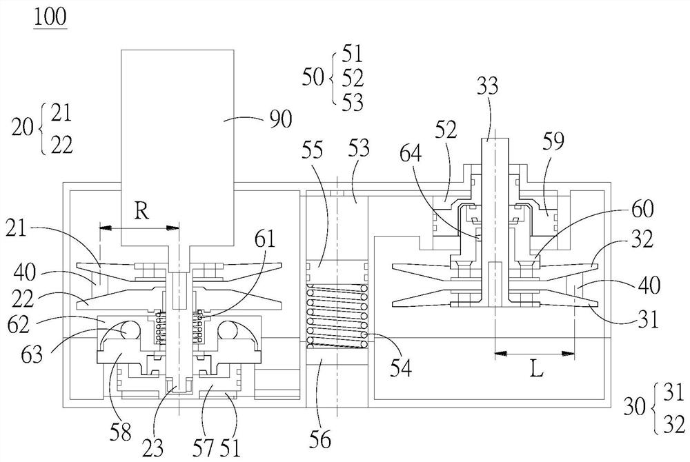
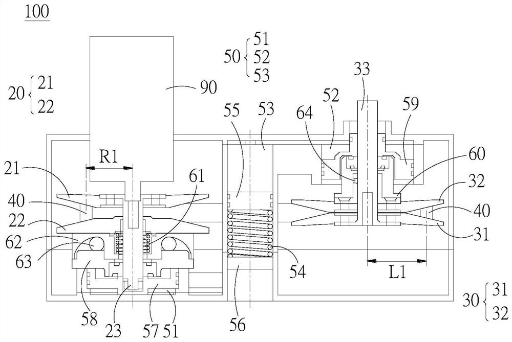
[0060] figure 2 It is a schematic diagram of the speed change mechanism of the electric locomotive according to the embodiment of the present inve...


PUM


Abstract

The invention discloses a variable transmission mechanism of electric motorcycles. The variable transmission mechanism comprises a driving belt pulley set, a driven belt pulley set, a transmission belt and an oil pressure device. The driving belt pulley set moves in the axial direction of the input shaft so as to adjust the first pitch circle radius. The driven belt wheel set moves in the axial direction of the output shaft so as to adjust the second pitch circle radius. The transmission belt is connected with the driving pulley set and the driven pulley set. The oil pressure device comprises a driving end cylinder body arranged on the driving belt pulley set and a driven end cylinder body arranged on the driven belt pulley set, the driving end cylinder body and the driven end cylinder body are communicated through a pressure groove, and pressure in the groove provides thrust for the driving belt pulley and the driven belt pulley so as to keep clamping force on the transmission belt.

Description

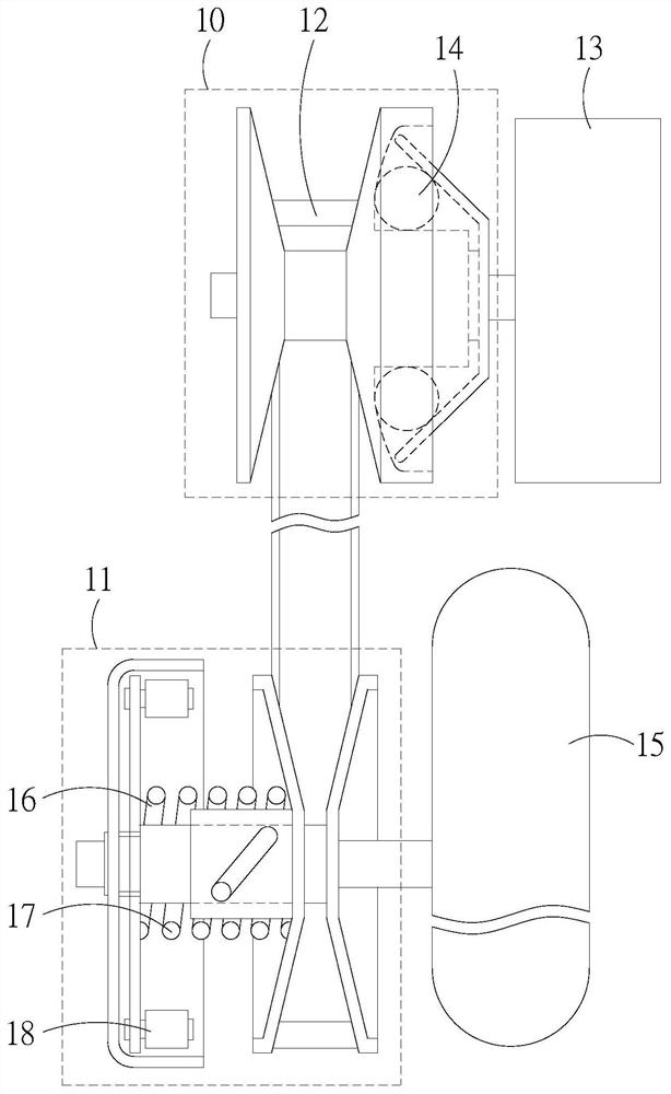
technical field [0001] The invention relates to the field of speed change mechanisms of electric locomotives, in particular to a speed change mechanism of electric locomotives which prevents transmission belts from slipping through an oil pressure device. Background technique [0002] On a locomotive that traditionally uses a fuel engine, a continuously variable transmission (Continuously Variable Transmission, CVT) is installed to drive the locomotive. Such as figure 1 As shown, the transmission device includes a drive pulley set 10 , a driven pulley set 11 and a drive belt 12 . The drive pulley set 10 is connected to the fuel engine 13 and rotates as the fuel engine 13 runs. When the drive pulley set 10 rotates, as the speed increases, the centrifugal force of the centrifugal roller 14 also increases and pushes the movable drive pulley to produce axial displacement, thereby changing the position of the drive belt 12 in the drive pulley set 10 (pitch circle diameter chan...

Claims


Application Information

Patent Timeline
IPC IPC(8): F16H7/02H02K7/10
CPCF16H7/02F16H2007/0865H02K7/1008Y02T10/64
Inventor 吴健铭邹忠全王东勋王柏翔王政杰王楷茵
Owner 吴健铭
Learn More