
High-density polymer grouting reinforcement method for roadbed at sinking position of bridge and culvert butt strap

A grouting reinforcement and high-density technology, applied in the direction of roads, roads, road bottom, etc., can solve problems that even exceed 60cm, settlement fractures at bridge heads and abutment backfill, and no further in-depth research on the grouting mechanism.

Inactive Publication Date: 2021-04-09
河南长安交通科技发展有限公司
View PDF4 Cites 2 Cited by
  • Summary
  • Abstract
  • Description
  • Claims
  • Application Information

AI Technical Summary

Problems solved by technology

[0003] At present, there is a common problem in high-grade highways: with the increase of the traffic period, different degrees of settlement fractures appear in the backfill of the bridge head and abutment back (the settlement value is generally 10-30cm, and some even exceed 60cm).
At present, domestic and foreign scholars mainly study the rheological characteristics and diffusion mechanism of chemical grout materials by referring to the grouting theory of cement grouting materials and combining the experimental simulation method. The research results are mainly reflected in sandy soil layers, rock masses and embankments. In engineering geology, etc., it involves the theory of seepage grouting and splitting grouting, but there is no further research on the grouting mechanism analysis of high polymer slurry materials in the repair of structural layers such as roadbed and pavement

Method used


Image

  • High-density polymer grouting reinforcement method for roadbed at sinking position of bridge and culvert butt strap
  • High-density polymer grouting reinforcement method for roadbed at sinking position of bridge and culvert butt strap
  • High-density polymer grouting reinforcement method for roadbed at sinking position of bridge and culvert butt strap

Examples


Embodiment 1

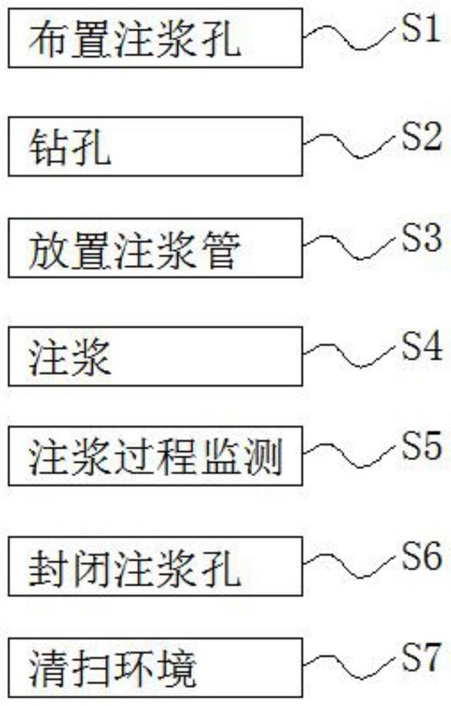
[0028] see figure 1 , a method for reinforcing a subgrade with high-density polymer grouting at the subsidence of bridge and culvert slabs, comprising the following steps:

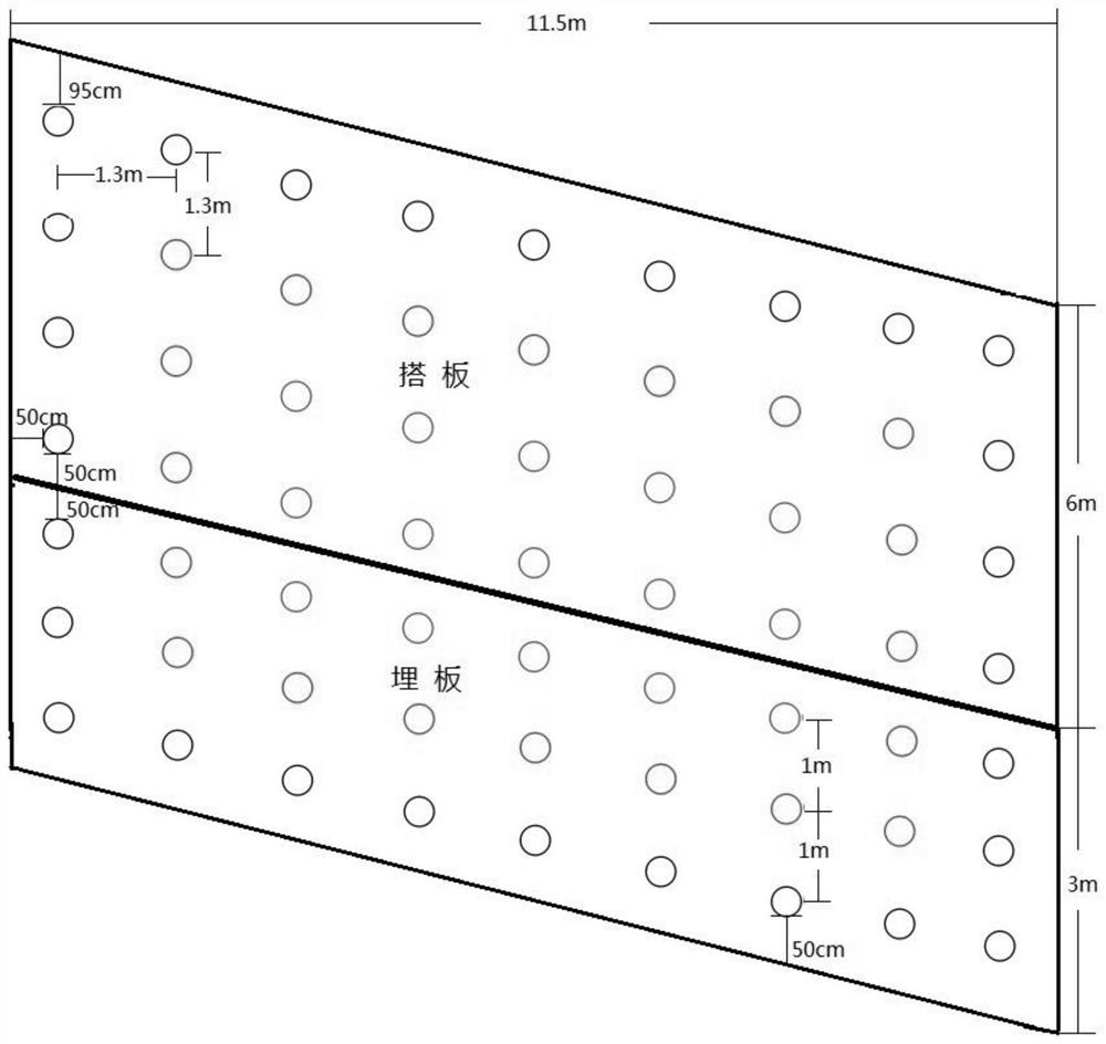
[0029] S1. Layout of grouting holes: arrange the grouting holes according to the site conditions, such as figure 2 As shown, the range of grouting hole distance is 1m-1.3m;

[0030] S2. Drilling: use a hollow drill to drill through the cement panel and the road base, and the drilling is divided into shallow drilling and deep drilling;

[0031] S3. Placing grouting pipes: The roadbed under the slab is reinforced by grouting, which is divided into two layers, located at 1.3m and 2m respectively, and the placement depths of the grouting pipes are 1.3m and 2m respectively;

[0032] S4. Grouting: if image 3 As shown, the slabs of exposed bridges and culverts are composed of slabs and buried slabs. The lengths of the slabs are 6m and 3m respectively, the width of the half-width driveway is 11.5m, and the co...

Embodiment 2

[0043] A high-density polymer grouting reinforcement method for subgrades at subsidence of bridge and culvert slabs, comprising the following steps:

[0044] S1. Layout of grouting holes: arrange the grouting holes according to the site conditions, such as figure 2 As shown, the range of grouting hole distance is 1m-1.3m;

[0045] S2. Drilling: use a hollow drill to drill through the cement panel and the road base, and the drilling is divided into shallow drilling and deep drilling;

[0046] S3. Placing grouting pipes: The roadbed under the slab is reinforced by grouting, which is divided into two layers, located at 1.3m and 2m respectively, and the placement depths of the grouting pipes are 1.3m and 2m respectively;

[0047] S4. Grouting: if image 3 As shown, the slabs of exposed bridges and culverts are composed of slabs and buried slabs. The lengths of the slabs are 6m and 3m respectively, the width of the half-width driveway is 11.5m, and the construction area is about...

Embodiment 3

[0058] After adopting the method described in Example 1 for construction, we inspected the effect of grouting construction:

[0059] Measure the lifting amount of the subsidence board: to ensure that the grouting material fills the void in the subgrade within the grouting depth range of 2m, and has the effect of reinforcing the soft subgrade. During grouting construction, for areas with large subsidence, the uplift of each grouting point shall be <1mm. Measured after grouting, the accumulative uplift of the slab is about 2cm in the area with the largest subsidence. It proves that this grouting construction has obvious roadbed reinforcement, filling and lifting effects.

[0060] After the grouting construction, we drilled core samples in the emergency parking lane and the driving lane respectively, and took out 2 core samples in total. According to the core samples taken out, it can be judged that the structure of the upper layer (10cm) of the board, the board (25cm), and the...


PUM

PropertyMeasurementUnit
diameteraaaaaaaaaa
depthaaaaaaaaaa
depthaaaaaaaaaa

Abstract

The invention discloses a high-density polymer grouting reinforcement method for a roadbed at the sinking position of a bridge and culvert butt strap. The method comprises the following steps that S1, grouting holes are formed; S2, drilling is conducted, specifically, a hollow drill is used for drilling to penetrate through a cement panel and a pavement base layer; S3, grouting pipes are placed; S4, grouting is conducted, specifically, the grouting sequence is from outside to inside, a high-density polymer liquid material conducts grouting on the peripheral grouting holes firstly, then conducts grouting on the inner peripheral grouting holes and finally conducts grouting on the inner center grouting holes; S5, the grouting process is monitored; S6, the grouting holes are closed; and S7, the environment is cleaned. According to the high-density polymer grouting reinforcement method for the roadbed at the sinking position of the bridge and culvert butt strap, the pavement base layer is maintained and the roadbed is reinforced by injecting the double-component high-density polymer liquid material, the injected high-density polymer liquid rapidly generates a chemical reaction to form a solid, the solid rapidly expands with the same volume to fill gaps in a pavement structure, and controllable pressure is applied to surrounding media to compact the roadbed.

Description

technical field [0001] The invention belongs to the technical field of road construction, and in particular relates to a high-density polymer grouting reinforcement method for subgrades at subsidence of bridge and culvert slabs. Background technique [0002] As the mileage of highway construction in my country increases year by year, highway maintenance and reconstruction will become one of the important tasks of the highway construction industry. As of the end of 2017, the mileage of expressways in my country has reached 136,500 kilometers, which means that the national expressway network structure is gradually taking shape. Therefore, expressway construction is expected to enter a relatively stable period in the next five or six years, and road maintenance and reconstruction work will become One of the important tasks of the road construction industry. Taking preventive maintenance measures on the pavement can prevent and inhibit the development of potential diseases on th...

Claims


Application Information

Patent Timeline
Patent Type & Authority Applications(China)
IPC IPC(8): E02D3/12E01C3/04E01F5/00
CPCE01C3/04E01F5/005E02D3/123
Inventor 张凯玮马耀辉徐建李博韩晓燕刘晨曦张广伟安明帅张永军
Owner 河南长安交通科技发展有限公司
Learn More