
Automatic cooling and fire extinguishing charging pile

An automatic cooling and charging pile technology, which is applied in electric vehicle charging technology, charging stations, electric vehicles, etc., can solve problems such as spontaneous combustion of charging piles, increased heat of components, and elevated temperature of piles

Inactive Publication Date: 2021-04-09
景海瑞
View PDF5 Cites 5 Cited by
  • Summary
  • Abstract
  • Description
  • Claims
  • Application Information

AI Technical Summary

Problems solved by technology

[0003] When the charging pile is working, because the internal components of the charging pile are in working state at this time, the charging pile is often accompanied by heating during the charging process. The temperature of the pile body is high, and the superposition of the heat generated by the electrical components inside the pile body will make the temperature inside the pile body too high; or when the charging pile works for a long time, the temperature inside the charging pile will continue to rise; or It is the aging of components. The heat generated by each component will increase significantly, which will increase the temperature inside the pile. When the above situations occur, the heat dissipation device cannot discharge the heat inside the charging pile in time, resulting in the temperature of the charging pile. It will rise sharply, and in severe cases, charging piles may even spontaneously ignite.

Method used


Image

  • Automatic cooling and fire extinguishing charging pile
  • Automatic cooling and fire extinguishing charging pile
  • Automatic cooling and fire extinguishing charging pile

Examples


Embodiment Construction

[0025] The following examples are for illustrative purposes only and are not intended to limit the scope of the invention.

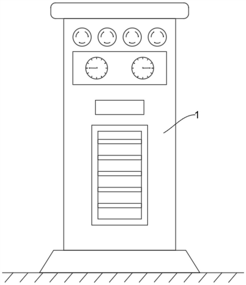
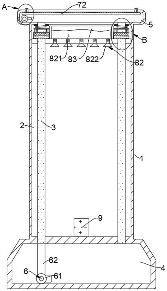
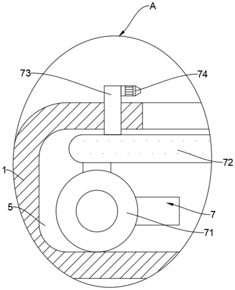
[0026] like Figure 1-6 As shown, a charging pile for automatic cooling and fire extinguishing includes a pile body 1, a cavity 2 is arranged in the pile body 1, and a plurality of vertical heat absorbing parts 3 are fixedly connected in the cavity 2, and the heat absorbing parts 3 are fixed by The cylinder 31 and the cooling plate 32 are composed of a plurality of cooling plates 32 and are vertically arranged. The cooling plate 32 is evenly and fixedly connected to the outside of the fixed cylinder 31, and the fixed cylinder 31 is fixedly connected to the upper top wall and the lower bottom wall of the cavity 2. .

[0027] The bottom end of the heat absorbing part 3 runs through the cavity 2 and communicates with the water storage chamber 4. The top end of the heat absorbing part 3 is connected with the sump 5. The top of the sump 5 is a slotted struct...


PUM


Abstract

The invention belongs to the field of charging piles, and particularly relates to an automatic cooling and fire extinguishing charging pile which comprises a pile body, a cavity is formed in the pile body, a plurality of vertical heat absorbing pieces are fixedly connected into the cavity, the bottom ends of the heat absorbing pieces communicate with a water storage cavity, the top ends of the heat absorbing pieces communicate with a water collecting tank, and a circulating mechanism is arranged in the water storage cavity. An atomization cooling mechanism is arranged in the water collecting tank, a fire extinguishing mechanism is fixedly connected to the top wall of the cavity, a detection mechanism is fixedly connected to the bottom wall of the cavity, and the detection mechanism controls the working states of the fire extinguishing mechanism, the circulating mechanism and the atomization cooling mechanism. The temperature in the pile body is reduced through the detection mechanism, water is used for absorbing heat of the charging pile in a normal state, then heat in the pile body is discharged through evaporation of atomized water, and when the pile body spontaneously combusts, high pressure is generated in the fire extinguishing cavity through cooperation of the pricking pin and the liquid storage bag to press out a fire extinguishing agent to achieve fire extinguishing.

Description

technical field [0001] The invention belongs to the field of charging piles, and in particular relates to a charging pile with automatic cooling and fire extinguishing. Background technique [0002] In urban air pollution, automobile exhaust emissions account for a large proportion, especially as the number of private cars increases and the proportion of specific gravity fluid increases. At present, as people pay more attention to environmental issues, new energy The development of automobiles is also getting faster and faster. In the process of the development of new energy vehicles, charging piles as supporting facilities for new energy vehicles are gradually distributed all over the country. [0003] When the charging pile is working, because the internal components of the charging pile are in working state at this time, the charging pile is often accompanied by heating during the charging process. The temperature of the pile body is high, and the superposition of the he...

Claims


Application Information

Patent Timeline
IPC IPC(8): B60L53/31B60L53/302A62C3/16A62C31/02
CPCB60L53/31B60L53/302A62C3/16A62C31/02Y02T10/70Y02T10/7072Y02T90/12
Inventor 景海瑞
Owner 景海瑞
Learn More