Bearing installer of small cabin and method for installing bearing by adopting installer

A technology of a mounter and a bearing, applied in the field of machinery, can solve the problems of mechanical damage to the cabin and the shaft sleeve, inability to meet the assembly requirements, and high assembly accuracy requirements, and achieve the effects of simple structure, uniform and symmetrical pressing force, and high assembly accuracy.

Active Publication Date: 2021-04-09
SHANXI JIANGHUAI HEAVY IND
View PDF14 Cites 2 Cited by
  • Summary
  • Abstract
  • Description
  • Claims
  • Application Information

AI Technical Summary

Problems solved by technology

Due to the narrow operating space of the cabin and high assembly precision requirements, assembly deflection will cause mechanical damage to the cabin and shaft sleeves, resulting in unusable products. Therefore, a successful assembly is required, and the traditional assembly method cannot meet the assembly requirements.

Method used


Image

  • Bearing installer of small cabin and method for installing bearing by adopting installer
  • Bearing installer of small cabin and method for installing bearing by adopting installer
  • Bearing installer of small cabin and method for installing bearing by adopting installer

Examples


Embodiment 1

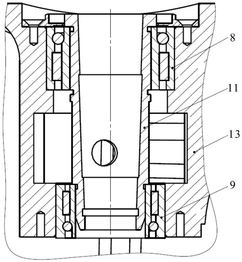
[0056] The assembly of bearing A 8 and bearing B 9 in the Ⅰ / Ⅲ quadrant shall be carried out according to the following steps:

[0057] ①First, assemble the inner ring 81 of bearing A and the shaft sleeve A11, such as Figure 4 shown;

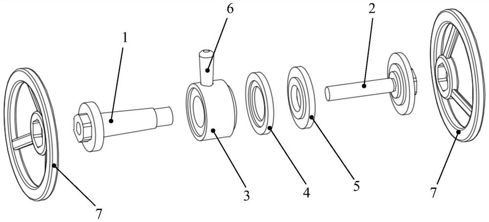
[0058] Put the big end of the shaft sleeve A11 downward on the outer tapered surface of the guide sleeve 1, and the taper direction of the two should be consistent; put the inner ring 81 of the bearing A on the outside of the shaft sleeve A11; place an adapter ring 3 on the On the end face of the inner ring 81 of bearing A, screw the guide rod 2 through the pressure ring 3 into the threaded hole of the guide sleeve 1, the positioning step of the guide rod 2 is closely matched with the pressure ring 3, continue to tighten the guide rod 1, and the bearing A The inner ring 81 is automatically aligned, and inserted into the sleeve A11 a little;

[0059] Place a turntable 7 on the workbench stably with the big end facing down, insert the head of th...

Embodiment 2

[0067] The assembly of bearing A8 and bearing C10 in quadrant Ⅱ / Ⅳ is carried out according to the following steps:

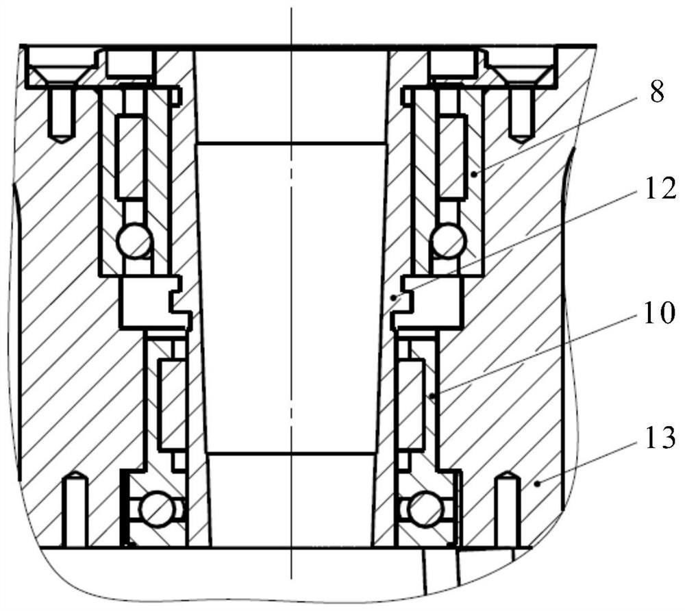
[0068] ① First, assemble the inner ring 81 of bearing A and the bushing B12, such as Figure 7 As shown, the assembly principle is the same as that of the bearing A inner ring 81 and the shaft sleeve A11 in Embodiment 1; the difference is that the placement direction of the bearing A inner ring 81 is different, and the placement direction is based on the II / IV quadrant of the cabin body 13 The installation direction of the bearing A 8 is determined.

[0069] ②Secondly, carry out the assembly of the outer ring 82 of the bearing A and the cabin body 13, such as Figure 8 As shown, the assembly principle is basically the same as the assembly of the bearing A outer ring 82 and the cabin body 13 in Embodiment 1; the difference is that the step of fitting the assembled bearing A inner ring 81 on the guide rod 2 is not included; Because of the small space inside the ...


PUM


Abstract

The invention relates to a bearing installer of a small cabin and a method for installing a bearing by adopting the installer. The bearing installer comprises a guide sleeve, a guide rod, a pressing ring, an adapter ring, a backing ring, a handle and a turntable, wherein matched internal and external threads are arranged on the screwing part of the guide sleeve and the guide rod, and the external turntable is rotated to drive the guide sleeve and the guide rod to be screwed together so as to provide press-in power required during bearing assembly; the guide sleeve and the guide rod are provided with positioning steps for positioning the bearing and a workpiece; the pressing ring, the adapter ring and the backing ring are part families adapting to different installation requirements; and the handle is installed on the pressing ring, the pressing ring is limited not to rotate and is kept static relative to the end face of the bearing, and the bearing is protected against damage caused by sliding friction in the assembling process. The bearing installer is simple in structure and convenient to operate, integrates guiding, positioning and press-in functions, and can assemble the bearing at a time, the phenomena of repeatedly disassembling and assembling the bearing and damaging a cabin body, a shaft sleeve and the bearing are avoided, and the problem of bearing assembly of a small cabin body is effectively solved.

Description

technical field [0001] The invention belongs to the field of machinery, and in particular relates to a bearing installer for a small cabin and a method for installing a bearing by using the installer. Background technique [0002] At present, when the bearing is assembled, it is usually installed by knocking, press-in, heating or freezing. Taking a small cabin as an example, three types of bearings are installed, such as figure 2 , image 3 As shown; where bearing A 8 and bearing B9 are split bearings, and bearing C10 is an integral bearing; the inner ring 81 of bearing A is installed on the big end of the shaft sleeve A11 and shaft sleeve B12, and the outer ring is installed on the outer side of the cabin body 13. In the installation hole; the inner ring of the bearing B9 is installed on the small end of the shaft sleeve A11, and the outer ring is installed in the bearing installation hole inside the cabin body 13; the inner ring of the bearing C10 is installed on the sma...

Claims


Application Information

Patent Timeline
IPC IPC(8): B23P19/02
CPCB23P19/02
Inventor 王卫勇陈岩梁耀江杨向伟
Owner SHANXI JIANGHUAI HEAVY IND
Why Eureka
Try Eureka