Clamping device and method for testing fatigue performance of twisted steel bar

A threaded steel bar and clamping device technology, which is applied in the field of fatigue testing, can solve problems such as low success rate, threaded steel bar broken in the jaws, and inability to accurately measure the number of threaded steel fatigue damages, so as to avoid damage and fracture of threaded steel bar, improve The effect of success rate and accuracy, fast and efficient connection

Pending Publication Date: 2021-04-06
中钢集团郑州金属制品研究院股份有限公司 +1
View PDF0 Cites 0 Cited by
  • Summary
  • Abstract
  • Description
  • Claims
  • Application Information

AI Technical Summary

Problems solved by technology

At present, when carrying out fatigue tests on threaded steel bars, the jaws of the fatigue testing machine are mostly used to directly clamp the two ends of the threaded steel bars for testing, so that the tangential force generated by the horizontal bite of the jaws can easily cause damage to the steel bars. The damaged part often produces stress concentration, causing the threaded steel bar to break in the jaws, and the fatigue test of the threaded steel bar cannot be carried out smoothly. Therefore, the success rate of the fatigue performance test of the threaded steel bar using the traditional clamping method is low and cannot be accurately measured Fatigue failure times of rebar

Method used


Image

  • Clamping device and method for testing fatigue performance of twisted steel bar
  • Clamping device and method for testing fatigue performance of twisted steel bar
  • Clamping device and method for testing fatigue performance of twisted steel bar

Examples


Embodiment 1

[0042] A kind of method of testing threaded steel bar fatigue performance of embodiment one is realized by following steps:

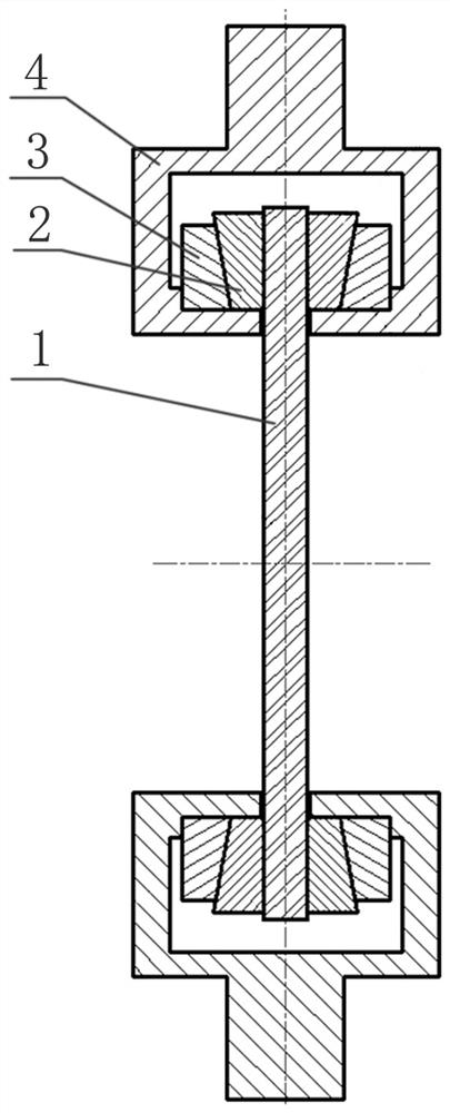
[0043] A. Select a threaded steel bar sample 1 with a designation of PSB830 and a nominal diameter of 15 mm, and select two sets of matching clips 2, tapered sleeves 3 and connectors 4 according to the diameter of the threaded steel bar sample 1;

[0044] B. According to the stroke of the fatigue testing machine and the length of the clamping device, the length of the threaded steel bar sample 1 is determined to be 1100mm, and the relative distance between the two connectors 4 is determined to be 800mm according to the length of the threaded steel bar sample 1 (that is, two The distance between the lower cavity wall of the connector 4);

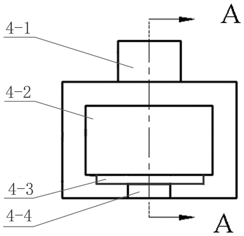
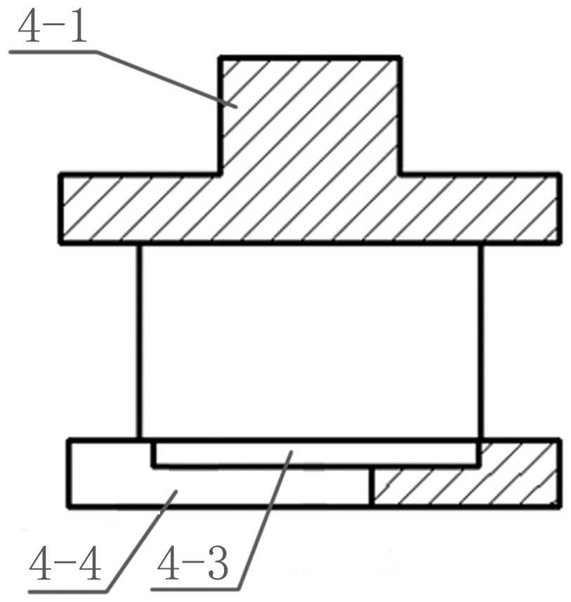
[0045] C. Start the fatigue testing machine, so that the upper and lower jaws of the fatigue testing machine respectively clamp the clamping ends 4-1 of the two connectors 4, and the two connectors 4 are symmetrically ...

Embodiment 2

[0051] A kind of method of testing threaded steel bar fatigue performance of embodiment two is realized by following steps:

[0052] A. Select a threaded steel bar sample 1 with a designation of PSB830 and a nominal diameter of 32 mm, and select two sets of matching clips 2, tapered sleeves 3 and connectors 4 according to the diameter of the threaded steel bar sample 1;

[0053] B. According to the stroke of the fatigue testing machine and the length of the clamping device, the length of the threaded steel bar sample 1 is determined to be 1200mm, and the relative distance between the two connectors 4 is determined to be 900mm according to the length of the threaded steel bar sample 1 (that is, two The distance between the lower cavity wall of the connector 4);

[0054] C. Start the fatigue testing machine, so that the upper and lower jaws of the fatigue testing machine respectively clamp the clamping ends 4-1 of the two connectors 4, and the two connectors 4 are symmetrically ...

Embodiment 3

[0060] A kind of method of testing threaded steel bar fatigue performance of embodiment three is realized by following steps:

[0061] A. Select a threaded steel bar sample 1 with a designation of PSB830 and a nominal diameter of 75 mm, and select two sets of matching clips 2, tapered sleeves 3 and connectors 4 according to the diameter of the threaded steel bar sample 1;

[0062] B. According to the stroke of the fatigue testing machine and the length of the clamping device, the length of the threaded steel bar sample 1 is determined to be 1100mm, and the relative distance between the two connectors 4 is determined to be 800mm according to the length of the threaded steel bar sample 1 (that is, two The distance between the lower cavity wall of the connector 4);

[0063] C. Start the fatigue testing machine, so that the upper and lower jaws of the fatigue testing machine respectively clamp the clamping ends 4-1 of the two connectors 4, and the two connectors 4 are symmetricall...


PUM

PropertyMeasurementUnit
Central angleaaaaaaaaaa

Abstract

The invention discloses a clamping device and method for testing fatigue performance of a twisted steel bar, and belongs to the technical field of fatigue testing. The device comprises two sets of clamping devices which are symmetrically clamped at the two ends of a twisted steel bar sample (1) and are composed of clamping pieces (2), conical sleeves (3) and connectors (4) which are sequentially nested from inside to outside, and quick connection and disassembly are achieved through the connectors (2) and a fatigue testing machine; and cyclic loading force is transmitted to the twisted steel bar test sample (1) step by step through the connectors (2) and the conical sleeves (3) and the clamping pieces (2) which are nested in sequence so as to carry out fatigue test. According to the invention, clamping parts at two ends of the twisted steel bar can be effectively prevented from being damaged, a fatigue test of the twisted steel bar can be guaranteed to be smoothly carried out, the fatigue damage frequency can be guaranteed to be accurately measured, a reliable technical basis is provided for judging the fatigue performance state and the fatigue life of the twisted steel bar, and the success rate and the accuracy of the test are improved; in addition, the device has the advantage of being convenient to assemble and disassemble.

Description

technical field [0001] The invention belongs to the technical field of fatigue testing, and in particular relates to a clamping device and a method for testing the fatigue performance of threaded steel bars. Background technique [0002] Threaded steel bars are widely used in continuous beams of large bridges, hydropower dams, nuclear power plants and other engineering anchorage parts. Because threaded steel bars are subjected to repeated and periodic dynamic loads for a long time, threaded steel bars tend to produce fatigue fractures. Tensile fatigue performance test is very necessary. Fatigue test can simulate the actual use conditions, and provide relevant performance data for designers, manufacturers and users of threaded steel bars, so as to facilitate the safe use and performance improvement of threaded steel bars. At present, when carrying out fatigue tests on threaded steel bars, the jaws of the fatigue testing machine are mostly used to directly clamp the two ends o...

Claims


Application Information

Patent Timeline
IPC IPC(8): G01N3/04G01N3/32
CPCG01N3/04G01N3/32G01N2203/0005G01N2203/0067G01N2203/0073
Inventor 毛海波洪涛张平萍史铭楷孙兵团
Owner 中钢集团郑州金属制品研究院股份有限公司
Why Eureka
Try Eureka