
Underground substation ventilation shaft

A technology for underground substations and ventilation shafts, applied in substations, cooling/ventilation of substations/switchgear, closed substations, etc., can solve problems such as poor lighting effects of ventilation shafts, increased energy consumption of fans, and poor ventilation, etc., to achieve improvement Poor daylighting effect, reduced wind pressure, and reduced fan energy consumption

Inactive Publication Date: 2021-04-06
SHENZHEN POWER SUPPLY BUREAU
View PDF7 Cites 2 Cited by
  • Summary
  • Abstract
  • Description
  • Claims
  • Application Information

AI Technical Summary

Problems solved by technology

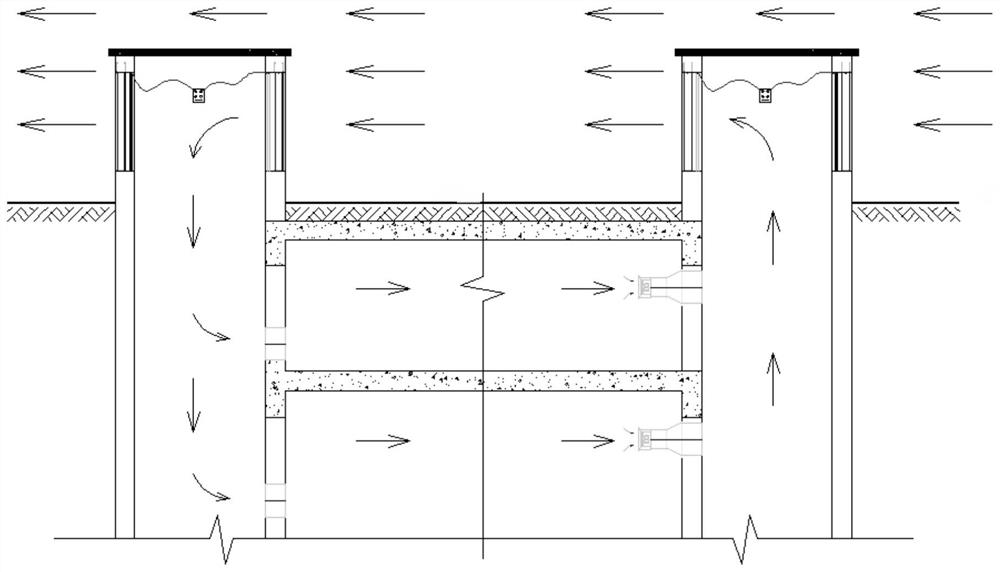
At present, most of the rain-proof ventilation shafts used in underground substations are fixed louver-type ventilation shafts, that is, the rain-proof louvers that enter and exit the wind are fixed on one side of the ventilation shaft, and the air enters the room or is discharged from the outside through the louvers on this side. When the wind direction changes due to seasonal changes, it will lead to poor ventilation and increased energy consumption of fans, which will affect the safe operation of substations, such as figure 1 shown
In addition, considering the environmental wind direction and the impact of rain leakage prevention, the shutters of the ventilation shaft are usually set on one side or adjacent two sides, and the lighting effect of the ventilation shaft is poor.

Method used


Image

  • Underground substation ventilation shaft
  • Underground substation ventilation shaft
  • Underground substation ventilation shaft

Examples


Embodiment Construction

[0023] The following descriptions of various embodiments refer to the accompanying drawings to illustrate specific embodiments in which the present invention can be implemented.

[0024] Please refer to figure 2 As shown, the embodiment of the present invention provides an underground substation ventilation shaft, including a symmetrically arranged air intake shaft for air intake and an exhaust shaft for exhaust air, and the air intake shaft and the exhaust shaft both include:

[0025] A structural wall 1 for separating the ventilation shaft from other rooms in the substation, the structural wall 1 partially protruding above the ground;

[0026] Rain-proof shutters 2 respectively embedded in the structural walls above the ground;

[0027] The electric glass window arranged on the inner side of the rain-proof shutter 2 is electrically connected to the electric device 4, and the opening and closing are controlled by the electric device 4;

[0028] The air inlet and outlet 6 a...


PUM


Abstract

The invention discloses an underground substation ventilation shaft. The underground substation ventilation shaft comprises an air inlet shaft for air inlet and an air exhaust shaft for air exhaust, wherein the air inlet shaft and the air exhaust shaft are symmetrically arranged; the air inlet shaft and the air exhaust shaft each comprise a structural wall body, rainproof shutters, electric glass windows, air inlets and outlets and a draught fan, wherein the structural wall bodies are used for separating the ventilation shaft from other rooms of a substation and partially protrude out of the ground; the rainproof shutters are embedded in the structural wall bodies on the ground; the electric glass windows are arranged on the inner sides of the rainproof shutters, electrically connected with electric devices and controlled by the electric devices to be opened and closed; the air inlets and outlets are formed in the underground portions of the structural wall bodies and used for airflow circulation between the ventilation shaft and other rooms of the substation; and the draught fans are used for providing power for airflow circulation. The problem that adverse wind ventilation is not smooth due to wind direction change is avoided, and meanwhile the problem that the lighting effect of the ventilation shaft is poor can be solved under the condition that ventilation is guaranteed.

Description

technical field [0001] The invention relates to the technical field of substation equipment, in particular to an underground substation ventilation shaft. Background technique [0002] The functional room of the underground substation is located below the ground, and there are a large number of large electrical equipment inside the room. It is necessary to remove indoor waste heat, humidity and toxic and harmful gases through mechanical ventilation to ensure the safe operation of the substation. The fan room is usually installed in the underground substation. The indoor air is discharged outside through the fan installed in the fan room, and the air with residual heat and humidity is sent into the ground environment through the ventilation shaft, and the fresh air on the ground passes through other ventilation. The well enters the substation room and maintains a slight positive or negative pressure in the room. [0003] Usually, the rainproof ventilation shaft of the underg...

Claims


Application Information

Patent Timeline
Patent Type & Authority Applications(China)
IPC IPC(8): E04F17/04H02B1/56H02B7/08
CPCE04F17/04H02B1/565H02B7/08
Inventor 弓国军符国晖韦波蒋晓东周亚敏李福权罗展标苏伟平
Owner SHENZHEN POWER SUPPLY BUREAU
Learn More