
Fastening device suitable for welding of different hardware pipe fittings

A pipe fitting welding and fastening device technology, which is applied in welding equipment, auxiliary equipment, welding equipment, etc., can solve the problems of manual welding without protective measures, difficulty in ensuring weld quality, and increased use costs, so as to increase versatility, The effect of improving weld quality and reducing work intensity

Inactive Publication Date: 2021-04-06
广州兆之祥科技有限公司
View PDF0 Cites 4 Cited by
  • Summary
  • Abstract
  • Description
  • Claims
  • Application Information

AI Technical Summary

Problems solved by technology

[0002] At present, most of the hardware pipe fittings used by people are standard parts, and manual welding and other follow-up processing are required during installation. However, manual welding generally has no protective measures and requires staff to weld around the pipe fittings. This working method has the risk of burns. Possibly, it is difficult to ensure the quality of the weld seam. On the other hand, most automatic welding equipment is only suitable for welding some specified models and shapes of pipe fittings, which is expensive and increases the cost of use.

Method used


Image

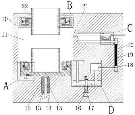
  • Fastening device suitable for welding of different hardware pipe fittings
  • Fastening device suitable for welding of different hardware pipe fittings
  • Fastening device suitable for welding of different hardware pipe fittings

Examples


Embodiment Construction

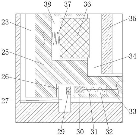
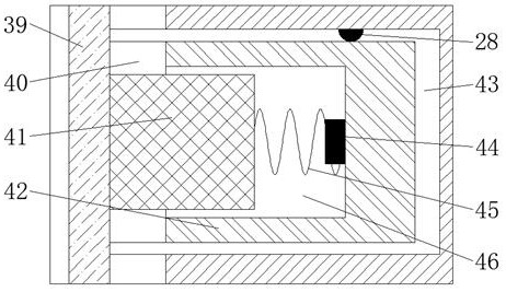
[0019] Combine below Figure 1-5 The present invention is described in detail, wherein, for the convenience of description, the orientations mentioned below are defined as follows: figure 1 The up, down, left, right, front and back directions of the projection relationship itself are the same.

[0020] A fastening device suitable for welding different hardware pipe fittings described in conjunction with accompanying drawings 1-5, includes a main body box 10, a welding cavity 11 is provided inside the main body box 10, and a welding torch is connected to the right side of the welding cavity 11 Through cavity 21, the right side of the welding torch through cavity 21 is connected with a storage cavity 54, and the right side of the storage cavity 54 is provided with a power belt cavity 20, and the right end wall of the storage cavity 54 is rotationally fitted and connected and extends to the left. The reciprocating screw rod 52 in the left end wall of the storage cavity 54 and ex...


PUM


Abstract

The invention relates to the related field of hardware, and discloses a fastening device suitable for welding of different hardware pipe fittings. The fastening device comprises a main body box, wherein a welding cavity is formed in the main body box, a welding gun through cavity is formed in the right side of the welding cavity in a communicating mode, a storage cavity is formed in the right side of the welding gun through cavity in a communicating mode, a power belt cavity is formed in the right side of the storage cavity, and a reciprocating screw rod which extends leftwards into the left end wall of the storage cavity and extends rightwards into the power belt cavity is connected in the right end wall of the storage cavity in a rotating fit mode. According to the fastening device, the position of a sliding limiting block is controlled through a magnetic block to be matched with an electric welding gun to move left and right, so that a rotating chassis is automatically clamped when ascending, moreover, the pipe fittings with different shapes and models can be fastened and welded, then the universality is improved, and the cost is reduced; and meanwhile, the welding pipe fittings are driven to rotate at a constant speed in the welding cavity through the rotating chassis to be automatically welded, then the quality of a welding seam is improved, the operation intensity of workers is reduced, the working efficiency is improved, and the personal safety is protected.

Description

technical field [0001] The invention relates to the related field of hardware, in particular to a fastening device suitable for welding different hardware pipe fittings. Background technique [0002] At present, most of the hardware pipe fittings used by people are standard parts, and manual welding and other follow-up processing are required during installation. However, manual welding generally has no protective measures and requires staff to weld around the pipe fittings. This working method has the risk of burns. Possibly, it is difficult to guarantee the quality of the weld seam. On the other hand, most automatic welding equipment is only suitable for welding some specified models and shapes of pipe fittings, which is expensive and increases the cost of use. Contents of the invention [0003] The purpose of the present invention is to provide a fastening device suitable for welding different hardware pipe fittings, which can overcome the above-mentioned defects of the...

Claims


Application Information

Patent Timeline
IPC IPC(8): B23K9/12B23K9/32B23K37/053
CPCB23K9/12B23K9/32B23K37/053
Inventor 高征昭
Owner 广州兆之祥科技有限公司
Learn More