
Pipe forging forming device with middle flange and side wall holes

A technology for pipes and flanges, which is applied in the field of pipe forging forming devices, can solve the problems of time-consuming and laborious, long processing time and low degree of automation, and achieve the effects of reducing production costs, reducing process procedures, and improving production efficiency

Pending Publication Date: 2021-04-06
ZHENGZHOU RES INST OF MECHANICAL ENG CO LTD
View PDF0 Cites 0 Cited by
  • Summary
  • Abstract
  • Description
  • Claims
  • Application Information

AI Technical Summary

Problems solved by technology

[0003] However, most of the existing side walls of pipe materials use machining to process square holes, which takes a long time and is laborious and labor-intensive.
In addition, there are many mechanical equipment involved in the specific processing, which cannot be integrated, and the degree of automation is not high

Method used


Image

  • Pipe forging forming device with middle flange and side wall holes
  • Pipe forging forming device with middle flange and side wall holes
  • Pipe forging forming device with middle flange and side wall holes

Examples


Embodiment Construction

[0032] Specific examples are given below to further describe the technical solution of the present invention in a clear, complete and detailed manner. This embodiment is the best embodiment on the premise of the technical solution of the present invention, but the protection scope of the present invention is not limited to the following embodiments.

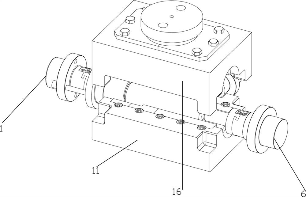
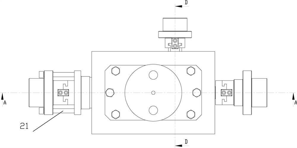
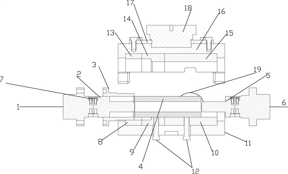
[0033] A pipe forging forming device with a central flange and side wall holes, comprising a pipe material 4, a push rod 12, and an upper die assembly, a lower concave die assembly, and a lower concave die assembly respectively located on the upper, lower, left, right, and rear sides of the pipe material 4. Die assembly, left punch 2, right punch 5, rear blanking assembly, the upper die assembly and the lower die assembly are symmetrically distributed with the middle horizontal section of the pipe material 4 as the symmetrical plane, and the rear The centerline of the blanking assembly is perpendicular to the centerline of the le...


PUM


Abstract

The invention discloses a pipe forging forming device with a middle flange and side wall holes. The pipe forging forming device comprises a pipe, ejector rods, an upper concave mold assembly, a lower concave mold assembly, a left punch, a right punch and a rear blanking assembly, wherein the upper concave mold assembly, the lower concave mold assembly, the left punch, the right punch and the rear blanking assembly are located at the upper part, the lower part, the left part, the right part and the rear part of the pipe separately; the upper concave mold assembly and the lower concave mold assembly are symmetrically distributed around the middle horizontal section of the pipe as the symmetrical surface; the center line of the rear blanking assembly perpendicularly intersects with the center lines of the left punch and the right punch and the center lines of the upper concave mold assembly and the lower concave mold assembly; the rear blanking assembly comprises a rear blanking convex mold connecting rod and a rear blanking convex mold; the lower concave mold assembly comprises a lower concave mold base, a lower concave mold I, a lower concave mold II and a lower concave mold III; the upper concave mold assembly comprises an upper concave mold base, an upper concave mold I, an upper concave mold II and an upper concave mold III; the left punch, the right punch, the lower concave mold I, the lower concave mold II and the lower concave mold III form a cavity; and the tube is horizontally put into the cavity after being heated. A multidirectional forming process is used, different areas of a pipe blank are heated to different temperatures, the middle flange of a pipe fitting is horizontally extruded and forged, and meanwhile, the side wall holes are punched.

Description

technical field [0001] The invention belongs to the technical field of metal thermal processing, and in particular relates to a tube forging forming device with a middle flange and side wall holes. Background technique [0002] At present, the forming process of cylinder forgings with middle flange and side wall holes is complicated. During the pier forging process of the flange in the middle of the pipe material, another area of ​​the pipe material is punched without a die. There is no die that can meet this requirement on the market. [0003] However, most of the existing side walls of pipe materials use machining to process square holes, which takes a long time and is time-consuming and labor-intensive. In addition, there are many mechanical equipment involved in specific processing, which cannot be integrated, and the degree of automation is not high. Contents of the invention [0004] In view of this, in order to solve the above-mentioned deficiencies in the prior a...

Claims


Application Information

Patent Timeline
IPC IPC(8): B21J13/02B21K1/14
CPCB21J13/02B21K1/14
Inventor 张超刘华刘百宣孙红星王涛刘光辉张义帅
Owner ZHENGZHOU RES INST OF MECHANICAL ENG CO LTD
Learn More