
Separated fishing cage formed by water pressure

A fishing cage and separate technology, which is applied in the field of fishing devices, can solve the problems of reducing the number of fish in the fishing cage, easy to die, and the mesh becomes larger, so as to improve the fishing effect, increase the catch rate, and improve the practicality. sexual effect

Inactive Publication Date: 2021-04-06
李体翠
View PDF7 Cites 1 Cited by
  • Summary
  • Abstract
  • Description
  • Claims
  • Application Information

AI Technical Summary

Problems solved by technology

[0002] Fish like to live in areas with many aquatic plants and rocks at the bottom of the river, and generally cannot use large-scale nets for fishing. At present, people usually use a fishing cage composed of a cage ring and a mesh cage when fishing. , Fishing cages are commonly used fishing tools. Generally, in the process of making mesh cages, manual knotting is used at the intersections of threads and threads. This method is relatively simple, and the effect is better when it is new. It has a certain degree of elasticity, and it will loosen after a long time of use, causing the mesh cage to deform and the mesh to become larger. Over time, the entire mesh cage will be in a mess, often causing fish to easily escape from the net, and the existing fishing cages generally They are all netted, and some fish will not go in after seeing the trapped fish inside, resulting in fewer fish in the fishing cage, and some fish cannot go to the water surface for a long time to breathe after entering the fishing cage, and they are prone to death, resulting in The quality of the fish in the fishing cage is low, and when some ferocious fish and milder fish are together, the ferocious fish will easily hunt other fish as food, further reducing the number of fish in the fishing cage

Method used


Image

  • Separated fishing cage formed by water pressure
  • Separated fishing cage formed by water pressure
  • Separated fishing cage formed by water pressure

Examples


Embodiment Construction

[0023] The following will clearly and completely describe the technical solutions in the embodiments of the present invention with reference to the accompanying drawings in the embodiments of the present invention. Obviously, the described embodiments are only some, not all, embodiments of the present invention.

[0024] Examples of the described embodiments are shown in the drawings, wherein like or similar reference numerals designate like or similar elements or elements having the same or similar functions throughout. The embodiments described below by referring to the figures are exemplary and are intended to explain the present invention and should not be construed as limiting the present invention.

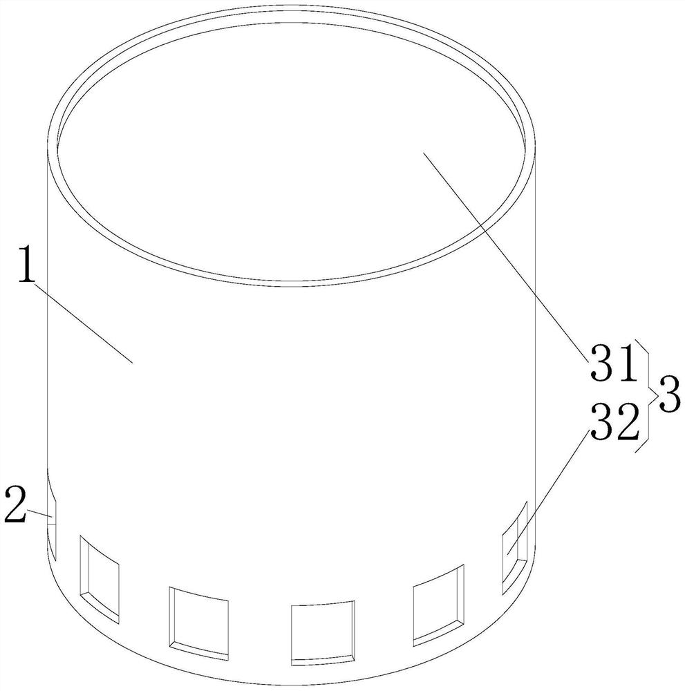
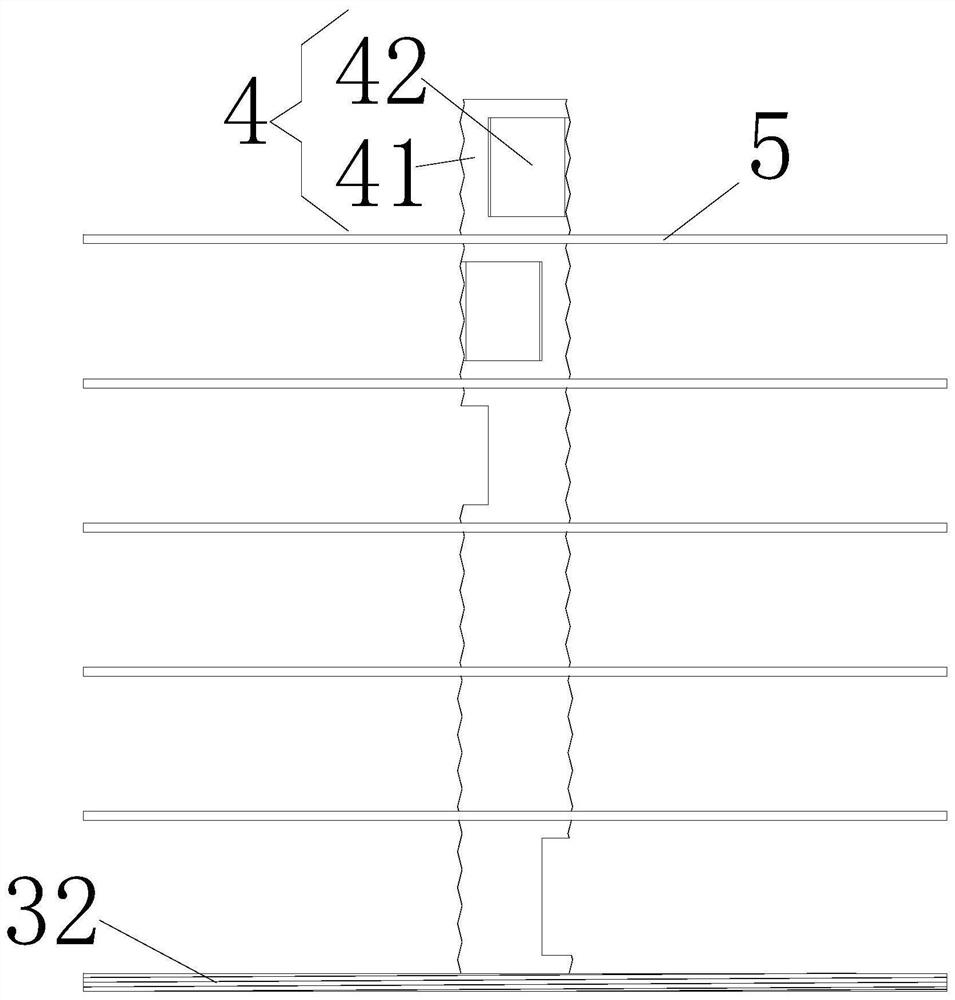
[0025] see Figure 1-5 , the present invention provides a technical solution: a separate fishing cage formed by water pressure, including a sealed fishing bucket 1, and the outer wall of the sealed fishing bucket 1 near the bottom is uniformly provided with a fish inlet slot...


PUM


Abstract

The invention discloses a separated fishing cage formed by water pressure and relates to the technical field of fishing devices. The separated fishing cage formed by water pressure comprises a sealed fishing sleeve barrel, fish inlet notches are evenly formed in positions, close to a bottom end, of an outer wall of the sealed fishing sleeve barrel, sealing and fixing mechanisms are arranged at an upper end and a lower end of the sealed fishing sleeve barrel, internal threads are arranged at positions, close to the sealing and fixing mechanisms, of an inner wall of the sealing fishing sleeve barrel, and a telescopic positioning mechanism is fixedly connected to a position, close to a center, of a top end of the sealing and fixing mechanism. The separated fishing cage formed by water pressure reduces vigilance of fishes, enables the fishes to enter the sealed fishing sleeve barrel more easily, and reduces a situation that fierce fishes prey other fishes. Oxygen can be provided for separated fishes after the fishes are separated and layered through arranged water pressure floating mechanisms, so that the fishes are prevented from suffocating and dying due to long-time trapping under water.

Description

technical field [0001] The invention relates to the technical field of fishing devices, in particular to a detached fishing cage formed by hydraulic pressure. Background technique [0002] Fish like to live in areas with many aquatic plants and rocks at the bottom of the river, and generally cannot use large-scale nets for fishing. At present, people usually use a fishing cage composed of a cage ring and a mesh cage when fishing. , Fishing cages are commonly used fishing tools. Generally, in the process of making mesh cages, manual knotting is used at the intersections of threads and threads. This method is relatively simple, and the effect is better when it is new. It has a certain degree of elasticity, and it will loosen after a long time of use, causing the mesh cage to deform and the mesh to become larger. Over time, the entire mesh cage will be in a mess, often causing fish to easily escape from the net, and the existing fishing cages generally They are all netted, and...

Claims


Application Information

Patent Timeline
Patent Type & Authority Applications(China)
IPC IPC(8): A01K69/08A01K63/04
CPCA01K69/08A01K63/042
Inventor 李体翠
Owner 李体翠
Learn More