
mouse trap

A mouse and cage technology, which is applied in the field of mouse capture cages, can solve the problems of reducing the vigilance of mice and the decrease of mouse catching rate, and achieve the effect of self-locking and quick reset, reducing vigilance and improving mouse catching rate

Active Publication Date: 2017-08-29
赵丝丝
View PDF4 Cites 0 Cited by
  • Summary
  • Abstract
  • Description
  • Claims
  • Application Information

AI Technical Summary

Problems solved by technology

As the vigilance of mice becomes stronger and stronger, the mouse catch rate of this method of placing bait in the cage begins to decline, and there is an urgent need for a new type of mouse cage that can reduce the vigilance of mice

Method used


Image

  • mouse trap
  • mouse trap

Examples


Embodiment Construction

[0014] The technical solution of the present invention will be further described below in conjunction with the accompanying drawings.

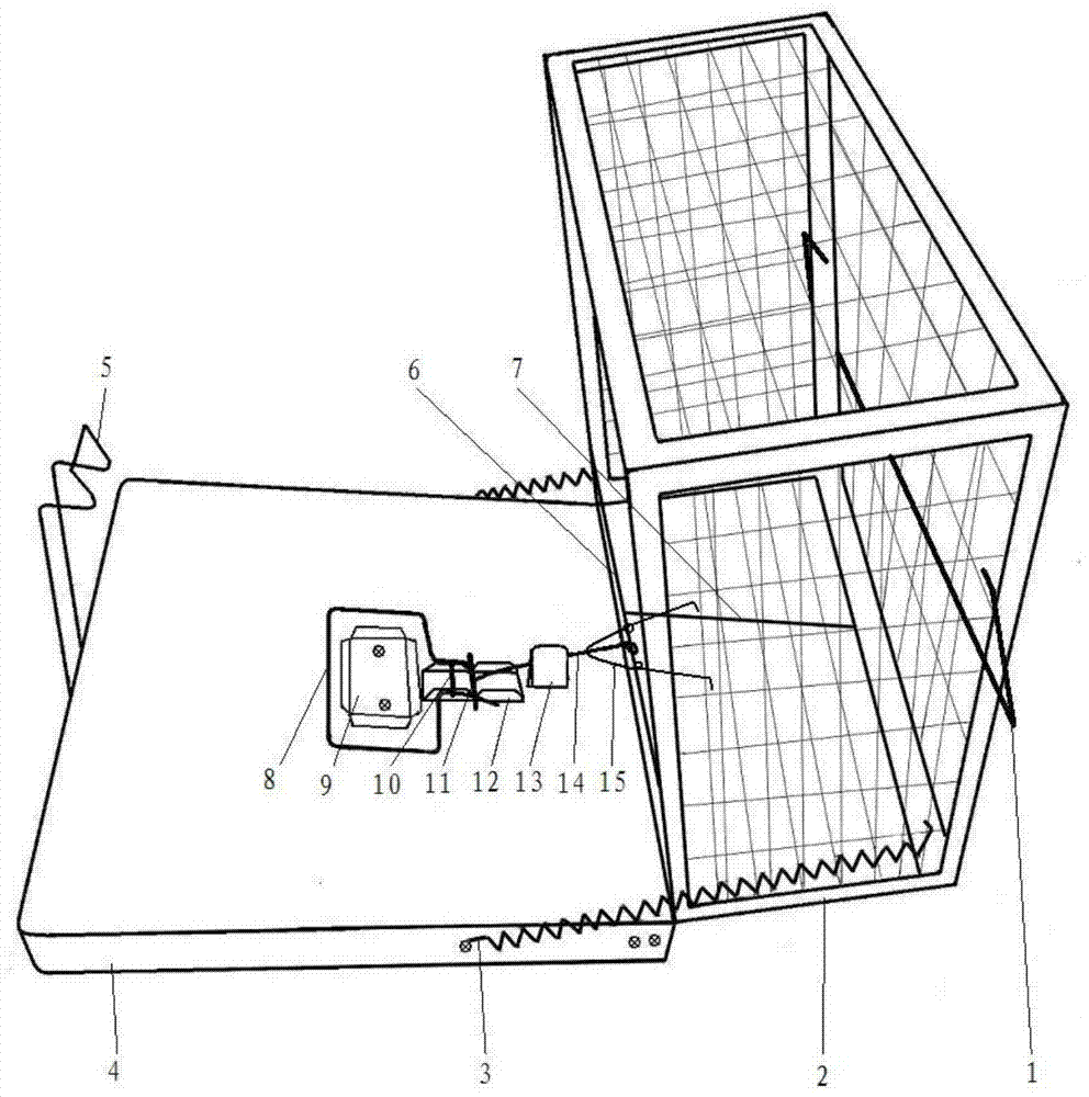
[0015] like Figure 1-Figure 2 Shown, a kind of mouse trapping cage comprises base body 4, cage body 2, self-locking spring 3, self-locking part 5 and touch device, one side of base body 4 is hinged with cage body 2 side, makes cage body 2 It can be opened or closed on the seat body 4 along the hinge; the bottom of the self-locking part 5 is connected to the other side of the seat body 4, and the top of the self-locking part 5 is provided for connecting the cage body 2 and the seat body 4 when the cage body 2 is closed. Locked card position.

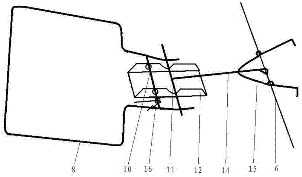
[0016] The touch device includes a touch ring 8, a rotating shaft 10, a return spring 16, a locking lever 11, a mounting seat 12, a push rod 14, an elastic pressing member 15 and a first connecting rod 6; the first connecting rod 6 is connected to the cage body 2, One end of the push rod 14 is buckled ...


PUM


Abstract

Provided is a mouse trapping cage. One side of a base body is hinged to one side of a cage body. The bottom of a self-locking part is connected with the other side of the base body. The top of the self-locking part is provided with a clamping position for locking the cage body and the base body. A first connecting rod is connected with the cage body. One end of a top rod and the first connecting rod are buckled. The other end of the top rod and the locking rod are connected. A spring pressing piece is installed on the first connecting rod. An installation base is fixed to the base body. A groove locking position is arranged at one end of the installation base so that the locking rod can be placed at the groove locking position when the cage body is opened and the opening state of the cage body can be kept. The other end of the installation base is fixedly connected with the tail portion of a trigger ring through a rotating shaft. A rotating shaft is sleeved with a reset spring. One end of the reset spring abuts against the base body, and the other end of the reset spring is connected with the tail portion of the trigger ring. The two ends of the locking rod are located at the tail portion of the trigger ring. When the trigger ring is pressed down, the tail portion of the trigger ring is lifted up so that the locking rod can be disengaged from the groove locking position. One end of the self-locking spring is connected with the base body, and the other end of the self-locking spring is connected with the cage body. The mouse trapping cage is sensitive in reaction, rapid in self-locking operation, and capable of reducing the vigilance of mice and increasing the mouse trapping rate.

Description

technical field [0001] The invention relates to a rat trapping cage. Background technique [0002] Present mouse cage mostly is that bait is placed inside cage body, after luring mouse enters cage body from cage door, touches control switch, thereby cage door is closed. Along with the vigilance of mice is getting stronger and stronger, the mouse catch rate of this mode that bait is placed in the cage body begins to decline, be badly in need of a kind of novel mouse cage that can reduce the vigilance of mice. Contents of the invention [0003] The technical problem to be solved by the present invention is to provide a rat trapping cage with higher rat trapping efficiency. [0004] The technical scheme adopted by the present invention to solve the above-mentioned technical problems is as follows: a mouse catching cage, comprising a seat body, a cage body, a self-locking spring, a self-locking part and a touch device, one side of the seat body is hinged to one side of the ca...

Claims


Application Information

Patent Timeline
Patent Type & Authority Patents(China)
IPC IPC(8): A01M23/22
Inventor 赵大量
Owner 赵丝丝
Learn More