Method for calculating through hole number and resistance value of cross-layer chain type connection structure
A technology of chain connection and connection structure, applied in computing, computer-aided design, electrical and digital data processing, etc., can solve problems affecting testing and analysis, result error, repeated calculation, etc., to achieve accurate results, reduce errors, and concise steps Effect
- Summary
- Abstract
- Description
- Claims
- Application Information
AI Technical Summary
Problems solved by technology
Method used
Image
Examples
Embodiment 1
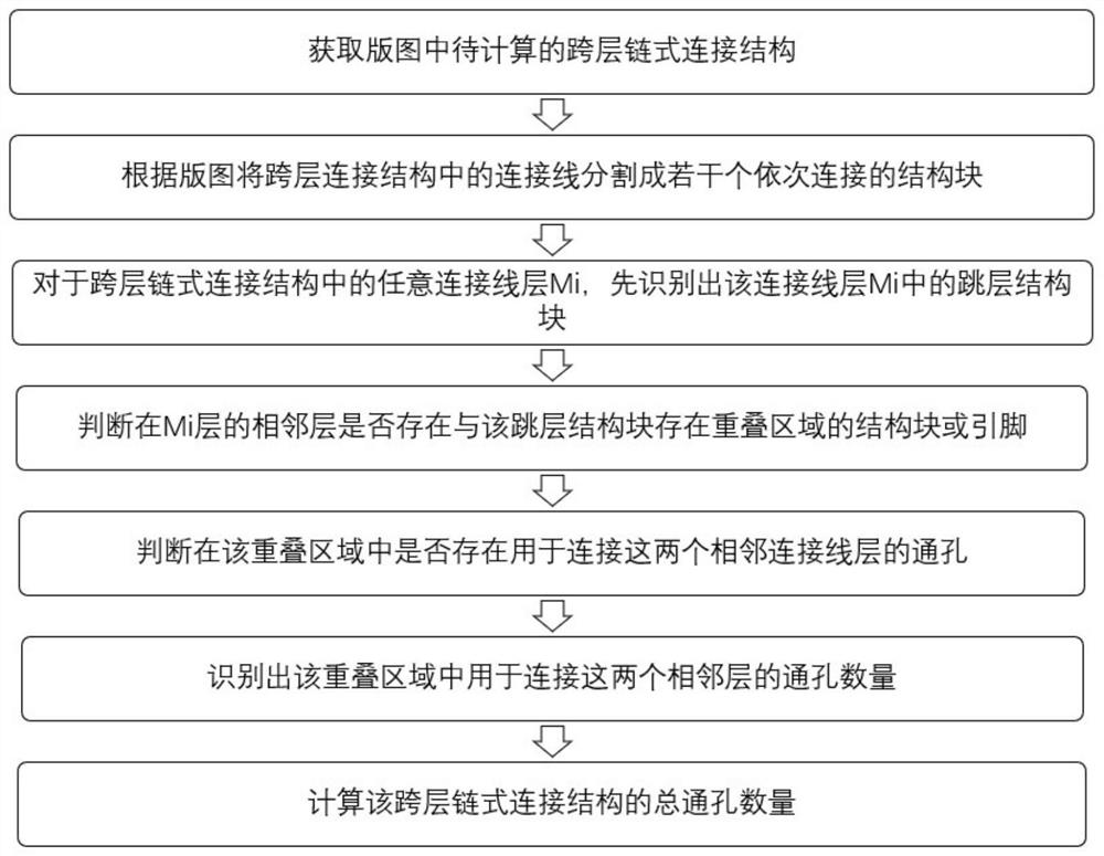
[0032] Such as figure 2 As shown, the method for calculating the number of vias in the cross-layer chain connection structure disclosed in Embodiment 1 of the present invention includes: step 1, obtaining the cross-layer chain connection structure to be calculated in the layout;
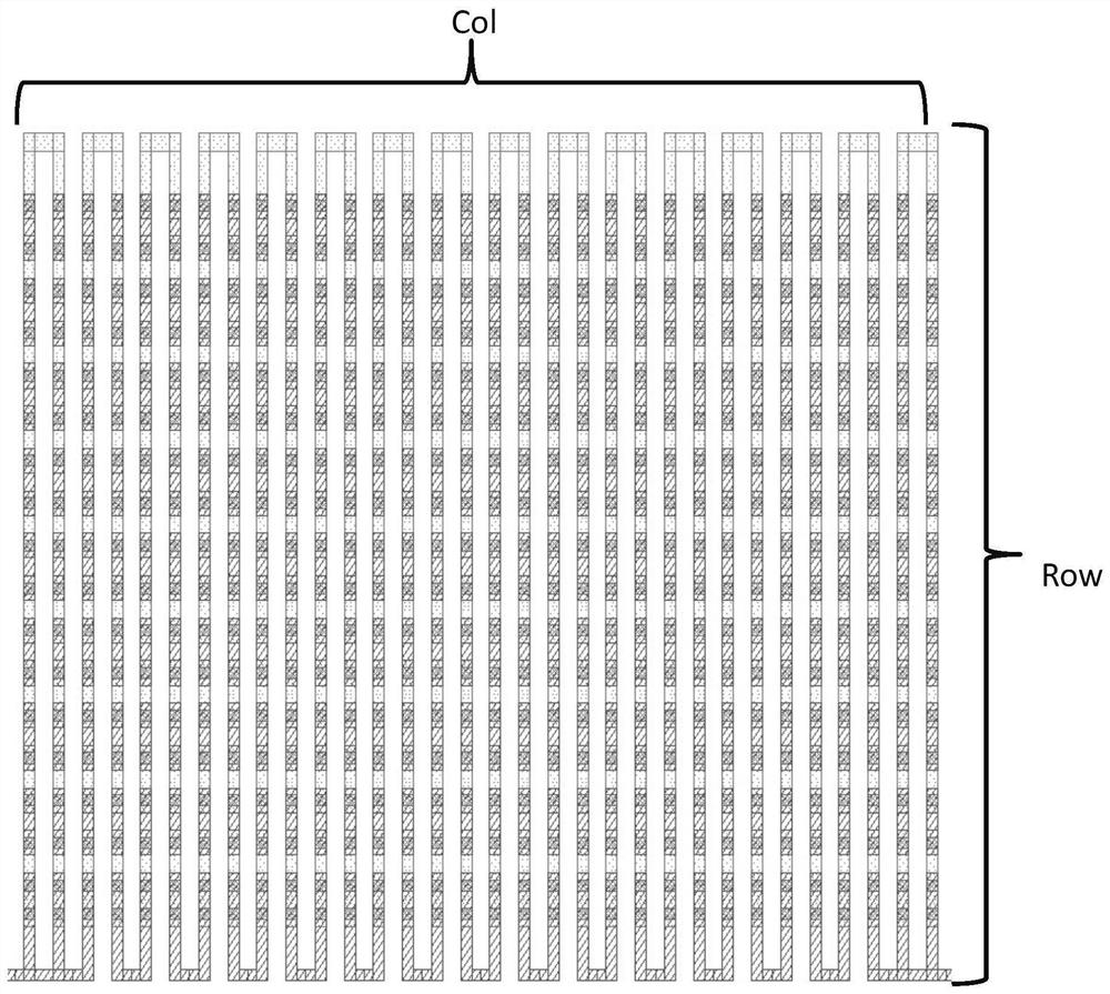
[0033] The cross-layer chain connection structure includes several connection lines and several through holes, and the connection lines are in the connection line layer M i , the vias are in the via layer V j in, and at V j The through holes in the layer are used to connect the connecting wires or pins (pins) in two adjacent connecting wire layers; where, i∈[1,E], j∈[1,F], E, F are greater than 1 of natural numbers. According to the layout, the connection lines in the cross-layer chain connection structure are divided into several sequentially connected structural blocks.
[0034] Such as image 3 As shown, in this embodiment, the cross-layer chain connection structure includes connecting lines...
Embodiment 2
[0042] In Embodiment 2, according to different application requirements, the method of calculating the resistance value of the cross-layer chain connection structure can further accurately calculate the resistance value of the cross-layer chain connection structure, and the calculation formula is as follows: ; wherein, the For connecting line layer M i The resistance value of the single-layer connection structure in the connection line layer M i The single-layer connection structure in includes M i The connection line in the layer; i∈[1,E], E is a natural number greater than 1. which gets the Specifically include: obtaining the number of squares of the single-layer connection structure; then multiplying the number of squares by the resistance of the square to obtain the resistance value of the single-layer connection structure . The L and W of the single-layer connection structure block in this embodiment are as shown in Figure 5 (a), in the layout, the single-layer c...
Embodiment 3
[0046] As shown in FIG. 6( a ), in this embodiment, when there is an overlap area between the end structure block polygon and the pin pin, the center point of the overlap area is taken as the common point G.
[0047] As shown in Figure 6(b), in this embodiment, when there is no overlapping area between the end structural block polygon and the pin pin but there is a shared side M, the shared side M overlaps with the length X of the end structural block polygon , the quadrilateral region S is extended from the common side M to the end structure block polygon, and the two adjacent sides of the quadrilateral region S are the shared side M and the width Y of the end structure block polygon respectively. The center point serves as the common point G.
[0048] As shown in Figure 6(c), in this embodiment, when there is no overlapping area between the end structural block polygon and the pin pin but there is a common side M, and the shared side overlaps with the width Y of the end struct...
PUM
 Abstract
Description
Claims
Application Information
 - R&D
- Intellectual Property
- Life Sciences
- Materials
- Tech Scout
- Unparalleled Data Quality
- Higher Quality Content
- 60% Fewer Hallucinations
Browse by: Latest US Patents, China's latest patents, Technical Efficacy Thesaurus, Application Domain, Technology Topic, Popular Technical Reports.
© 2025 PatSnap. All rights reserved.Legal|Privacy policy|Modern Slavery Act Transparency Statement|Sitemap|About US| Contact US: help@patsnap.com


