
Touch display apparatus

A touch display device, touch display panel technology, applied in static indicators, instruments, electrical digital data processing and other directions, to achieve the effect of improving the bonding yield, improving the impact, and shortening the distance

Inactive Publication Date: 2021-04-02
RAYDIUM SEMICON
View PDF0 Cites 0 Cited by
  • Summary
  • Abstract
  • Description
  • Claims
  • Application Information

AI Technical Summary

Problems solved by technology

The touch display panel includes a display module and a touch sensor

Method used


Image

  • Touch display apparatus
  • Touch display apparatus
  • Touch display apparatus

Examples


Embodiment Construction

[0066] Reference will now be made in detail to the exemplary embodiments of the present invention, examples of which are illustrated in the accompanying drawings. Elements / members with the same or similar numbers used in the drawings and embodiments are used to represent the same or similar parts.

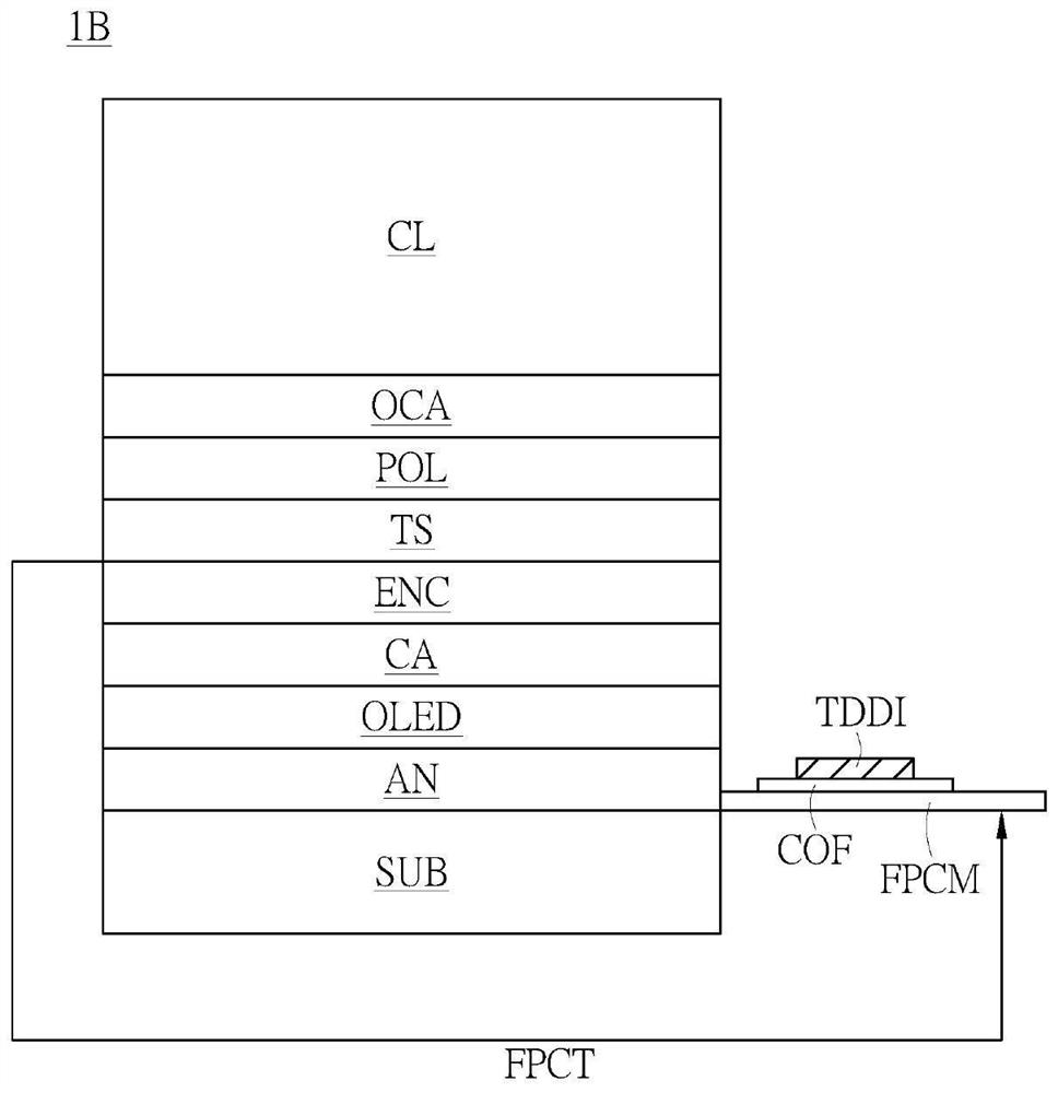
[0067] A specific embodiment according to the present invention is a touch display device. In this embodiment, the touch display device can be applied to a wearable device, which can include an organic light-emitting diode (OLED) panel with an on-cell touch sensing structure and a touch and display driver integration (TDDI) integrated circuit, and can be applied to various touch sensing technologies, such as mutual capacitance touch sensing and self capacitance touch sensing, but not limited thereto.

[0068] Please refer to Figure 5 , Figure 5 This is a schematic diagram of the touch display device in this embodiment.

[0069] Such as Figure 5 As shown, the touch display d...


PUM


Abstract

A touch display apparatus is disclosed. The touch display apparatus includes a touch display panel, a chip on film (COF) layer and a driving circuit. The touch display panel includes a display moduleand a touch sensor. The touch sensor is disposed on the display module. The COF layer includes a connecting portion and an extending portion connected to each other. The connecting portion is coupledto the display module, and the extending portion is coupled to the touch sensor. The driving circuit is disposed on the COF layer. The driving circuit transmits touch signals with the touch sensor through the COF layer and its extending portion.

Description

technical field [0001] The present invention relates to a display device, in particular to a touch display device. Background technique [0002] In the prior art, when an On-Cell touch display panel applied to a wearable touch display device is combined with a Touch and Display Driver (Touch and Display Driver) packaged in a Chip On Film (COF) package, Integration, TDDI) integrated circuit, because the touch sensor (Touch Sensor) contact of the On-Cell touch display panel is located on the upper glass, and the touch and display driver integration (TDDI ) The bonding position of the integrated circuit is located on the bottom glass of the display module. Therefore, the two need to be additionally coupled through a flexible printed circuit board (Flexible Printed Circuit, FPC) for touch control, so that the touch and display The driver integration (TDDI) integrated circuit and the touch sensor can transmit touch signals and can be connected to the Sensor. [0003] At present...

Claims


Application Information

Patent Timeline
Patent Type & Authority Applications(China)
IPC IPC(8): G06F3/044H01L27/32
CPCG06F3/0445H10K59/40H10K59/12G06F3/0412G06F3/04164H10K59/50G09G3/3208G06F3/044
Inventor 杨镇玮林政男
Owner RAYDIUM SEMICON
Learn More