A valve device with the functions of high-pressure low-speed oil injection and high-pressure high-speed oil discharge

A high-speed, valve device technology, applied in the direction of non-mechanical drive clutches, clutches, fluid-driven clutches, etc., can solve the problems of difficult design and processing of rotary seals, and the inability to realize oil filling and draining of rotary seals, so as to reduce design and processing effect of difficulty

Active Publication Date: 2022-04-08
中国船舶重工集团公司第七0三研究所
View PDF11 Cites 0 Cited by
  • Summary
  • Abstract
  • Description
  • Claims
  • Application Information

AI Technical Summary

Problems solved by technology

[0002] At present, the oil filling and oil draining of the rotary cylinder of the friction clutch generally adopts the method of connecting the oil source and the oil inlet passage of the rotary seal, but with the increase of the rotational speed and oil supply pressure of the friction clutch, the design and processing of the rotary seal become more and more difficult , the commonly used index to investigate the difficulty of the rotary seal is the PV value, P is the oil supply pressure, and V is the linear velocity of the rotary seal. In some occasions with a large PV value, it is even impossible to realize the oil injection and drain of the rotary seal.

Method used


Image

  • A valve device with the functions of high-pressure low-speed oil injection and high-pressure high-speed oil discharge
  • A valve device with the functions of high-pressure low-speed oil injection and high-pressure high-speed oil discharge
  • A valve device with the functions of high-pressure low-speed oil injection and high-pressure high-speed oil discharge

Examples


Embodiment Construction

[0023] The present invention is described in more detail below in conjunction with accompanying drawing example:

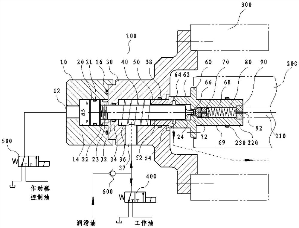
[0024] combine Figure 1-8 , the friction clutch rotary cylinder with micro-leakage or zero-leakage characteristics is rigidly installed on the connecting shaft 200, the connecting shaft 200 is supported on the support housing 300 through bearings, and the connecting shaft 200 rotates with the rotary cylinder. The core of the connecting shaft 200 is an oil passage 210, and the oil passage 210 communicates with the rotary oil cylinder. At the end of the connecting shaft 200, the actuator cylinder 10, the piston 20, the piston rod 23, the ejector rod 24, the adapter plate 30, the sealing spring, the rotary sealing static ring, the one-way valve body 60, the one-way valve core 70, The one-way valve spring 80 and the one-way valve spring baffle 90 are concentrically arranged and mechanically connected in sequence.

[0025] The one-way valve mounting hole 220 formed ...


PUM


Abstract

The purpose of the present invention is to provide a valve device with the functions of high-pressure low-speed oil injection and high-pressure high-speed oil discharge. It is connected to the end of the shaft of the micro-leakage rotary oil cylinder. On the housing, the one-way valve body is connected to the end of the connecting shaft. The left end surface of the one-way valve body is formed with a rotating seal moving ring, and the piston rod passes through the centers of the rotating sealing static ring and the moving ring. At low speed, the actuator solenoid valve is energized, the piston moves, the ejector rod pushes the one-way valve core, and at the same time the oil injection solenoid valve is energized, the high-pressure working oil passes through the radial oil inlet hole of the adapter plate, the radial gap between the rotary seal and the piston rod Flows into the check valve and fills the rotary cylinder with oil. At high speed, the actuator solenoid valve is energized, the ejector rod pushes the one-way valve core, and at the same time, the oil injection solenoid valve is powered off, and the oil inlet hole is connected with the solenoid valve oil return channel, which can realize the oil discharge of the rotary cylinder at high speed. During high-pressure low-speed oil injection and high-pressure high-speed oil discharge, the PV value of the rotary seal is small, and the life of the rotary seal is long.

Description

technical field [0001] The invention relates to a friction clutch, in particular to an oil valve of the friction clutch. Background technique [0002] At present, the oil filling and oil draining of the rotary cylinder of the friction clutch generally adopts the method of connecting the oil source and the oil inlet passage of the rotary seal, but with the increase of the rotational speed and oil supply pressure of the friction clutch, the design and processing of the rotary seal become more and more difficult , the commonly used index to investigate the difficulty of the rotary seal is the PV value, P is the oil supply pressure, and V is the linear velocity of the rotary seal. In some occasions with a large PV value, it is even impossible to realize the oil injection and drain of the rotary seal. Contents of the invention [0003] The purpose of the present invention is to provide a high-pressure oil pump that can inject oil at high oil pressure and low speed and drain oil...

Claims


Application Information

Patent Timeline
Patent Type & Authority Patents(China)
IPC IPC(8): F16D25/12
CPCF16D25/14
Inventor 闫泽战庆欣戴维泽芦清文高长伟
Owner 中国船舶重工集团公司第七0三研究所
Why Eureka
Try Eureka