Embedded column base joint

A technology of embedded column feet and joints, which is applied in the direction of basic structure engineering, architecture, building construction, etc., can solve the problem of the limited buried depth of the foundation cap, the influence of the space used on the ground floor of the building, and the inability to meet the calculation requirements of embedded column feet and other problems, to achieve the effect of eliminating the workload, improving the force form of the column foot, and increasing the height

Pending Publication Date: 2021-04-02
ABC BUILDING SYST CHINA
View PDF0 Cites 1 Cited by
  • Summary
  • Abstract
  • Description
  • Claims
  • Application Information

AI Technical Summary

Problems solved by technology

[0003] With the promotion and application of multi-storey steel structure industrial buildings, and considering factors such as earthquake resistance, the section of the steel pipe column at the bottom is getting larger and larger, so the thickness of the concrete foundation cap is required to be very large, but in many projects, the depth of the foundation cap is limited. , which cannot meet the calculation requirements for embedded column feet
The usual solution is to use outsourcing column feet, but this solution has a certain impact on the usable space on the ground floor of the building

Method used


Image

  • Embedded column base joint
  • Embedded column base joint
  • Embedded column base joint

Examples


Embodiment 1

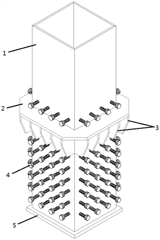
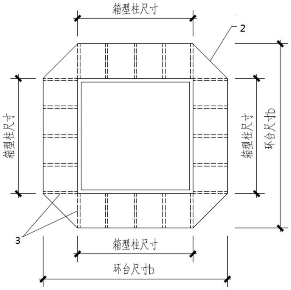
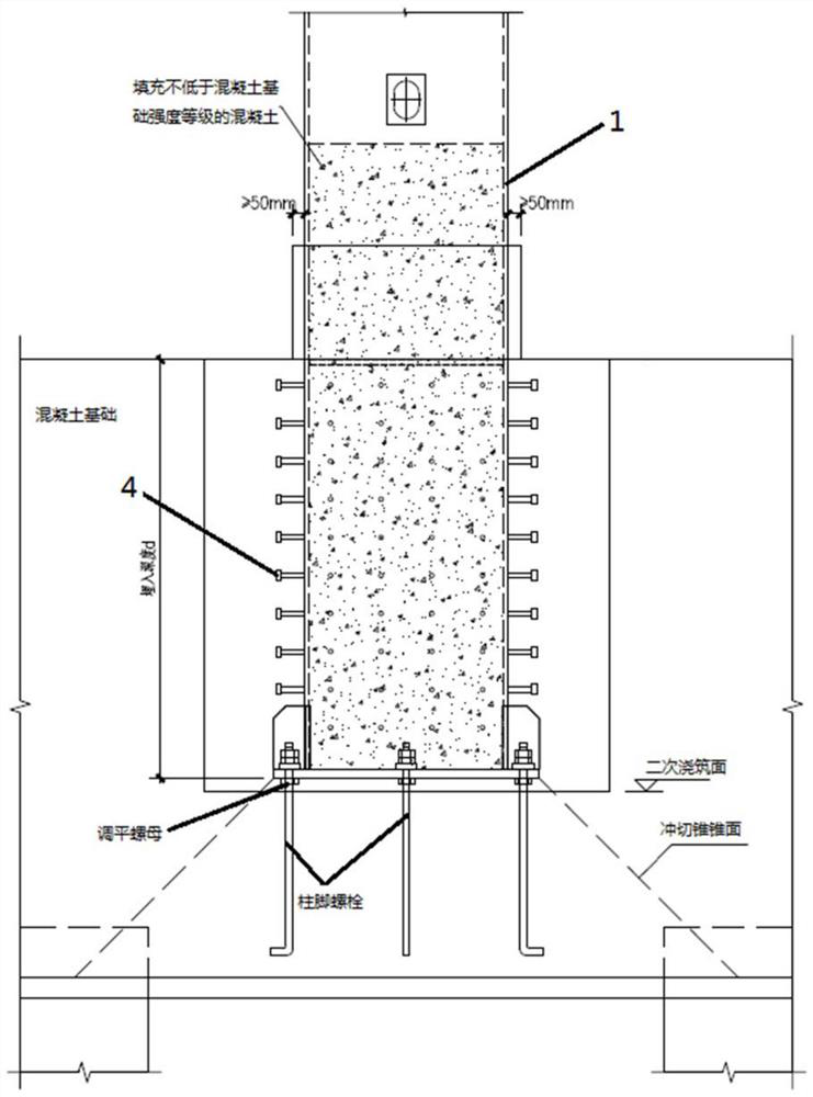
[0028] In the prior art, the form of the column base is as image 3 As shown, the bottom of the steel pipe column 1 is provided with a bottom plate 5. The steel pipe column 1 is a box-shaped column, and the box-shaped column is filled with concrete not lower than the strength level of the concrete foundation. The box-shaped column is inserted vertically in the concrete foundation. A stud 4 is provided on the column of the box column in the concrete foundation for resisting shear force. The cone surface of the punching cone is as image 3 As shown by the dotted line in the middle, at the bottom plate 5 of the steel pipe column 1 , in order to meet the load-bearing requirements, column foot bolts are installed on the bottom plate 5 . The transmission path of the force is as follows: part of the force is transmitted to the bottom plate 5 within the range of the column body, and then transmitted to the lower part of the concrete foundation, and the other part is transmitted to the ...


PUM


Abstract

The invention relates to an embedded column base joint. The embedded column base joint comprises a steel pipe column, a bottom plate is arranged at the bottom of the steel pipe column, a plurality ofstuds are arranged on the outer side of the column wall of the steel pipe column, an annular table sleeves the steel pipe column, the annular table comprises a through partition plate and a pluralityof stiffening plates, the through partition plate is perpendicularly connected with the column wall of the steel pipe column, and the stiffening plates are in polygon. The stiffening plates comprise top edges, inner side edges and outer side edges which are sequentially connected, the top edges are connected with the bottom face of the through partition plate, and the inner side edges are connected with the column wall of the steel pipe column. Compared with the prior art, the annular table is arranged to replace a bottom plate to transmit all vertical force to a concrete foundation, the punching face of the steel pipe column to the concrete foundation is transferred to the annular table from the column bottom, the height of a punching cone is greatly increased, under the condition that the burial depth of a concrete foundation bearing platform is limited, the requirement of the steel pipe column for the punching bearing capacity of the bearing platform is met, and the excavation workload is further reduced.

Description

technical field [0001] The invention relates to the technical field of construction engineering, in particular to an embedded column base node. Background technique [0002] With the continuous development of society, the construction industry has developed rapidly. In multi-storey steel structure industrial buildings, the column foot form is mostly box-shaped column embedded column foot. The usual method is as follows image 3 As shown, the bottom of the steel pipe column is provided with a bottom plate, and the steel pipe column is selected as a box-shaped column, and the box-shaped column is filled with concrete not lower than the strength level of the concrete foundation. The inner box columns are provided with studs on the columns to resist shear force. The cone surface of the punching cone is as image 3 As shown by the dotted line in the middle, at the bottom plate of the steel pipe column, in order to meet the load-bearing requirements, column foot bolts are also ins...

Claims


Application Information

Patent Timeline
Patent Type & Authority Applications(China)
IPC IPC(8): E04B1/24E04B1/58E04B1/41E02D27/42
CPCE02D27/42E04B1/2403E04B1/41E04B1/4157E04B2001/2463
Inventor 虞超
Owner ABC BUILDING SYST CHINA
Why Eureka
Try Eureka