Steel belt feeding and discharging equipment and implementation method thereof

A steel strip and equipment technology, applied in the field of steel strip loading and unloading equipment and its realization, can solve the problems of incapable steel strip hot rolling operation, incapable steel strip adjustment, steel strip unwinding deviation, etc. The material speed is stable, ensuring no breakage, and the effect of convenient tension

Pending Publication Date: 2021-04-02
东阳东磁自动化科技有限公司
View PDF16 Cites 0 Cited by
  • Summary
  • Abstract
  • Description
  • Claims
  • Application Information

AI Technical Summary

Problems solved by technology

[0003] There are some problems in the existing steel belt loading and unloading mechanism during use. For example, the position of the steel belt cannot be adjusted, and the steel belt is prone to deviation when unwinding, which may easily cause the steel belt to break; It is also not possible to perform hot rolling operations on the steel strip

Method used


Image

  • Steel belt feeding and discharging equipment and implementation method thereof
  • Steel belt feeding and discharging equipment and implementation method thereof
  • Steel belt feeding and discharging equipment and implementation method thereof

Examples


Embodiment 1

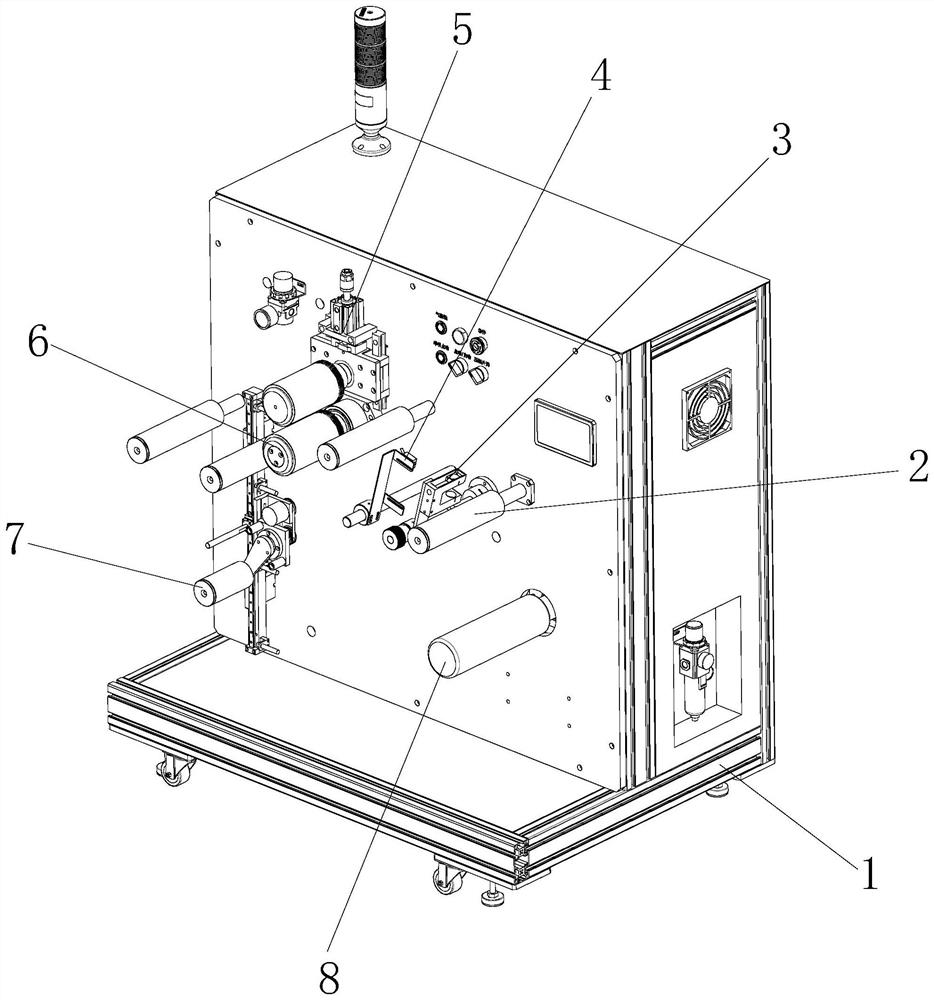
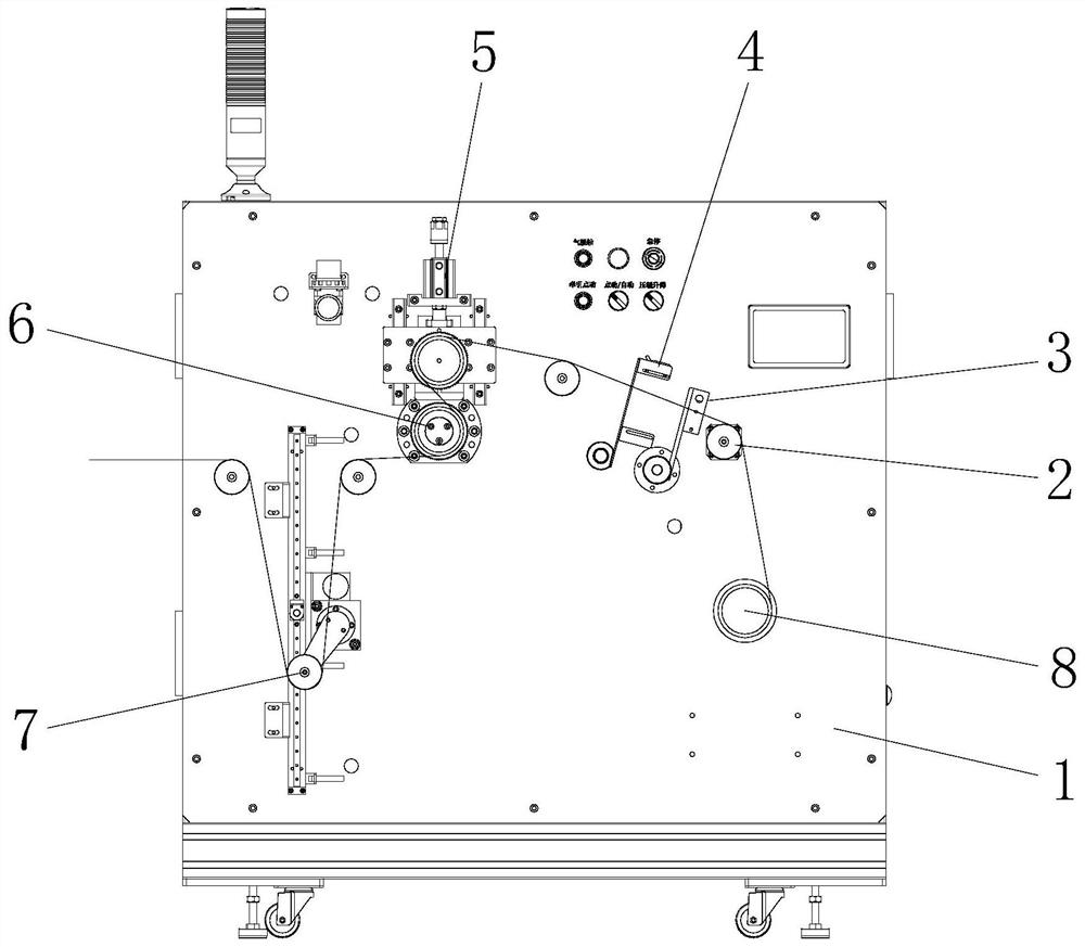
[0039] see Figure 1-9, the present invention provides the following technical solutions: a steel strip loading and unloading equipment, including a feeder and a feeder, the feeder includes a feeder frame 1, and the feeder frame 1 is provided with an air expansion shaft 8, The upper left corner of the air expansion shaft 8 is provided with an ultrasonic sensor 3 on the feeder frame 1, a photoelectric sensor 4 is provided on one side of the ultrasonic sensor 3, and a feeding driving roller 6 is provided on one side of the photoelectric sensor 4. The top of the material driving roller 6 is provided with a lifting roller lifting mechanism 5, the lower left corner of the feeding driving roller 6 is provided with a swinging roller mechanism 7, and several supporting rollers 2 are also provided on the feeding machine frame 1; Feeding machine frame 11, blanking machine frame 11 is provided with blanking driving roller 10, the top of blanking driving roller 10 is provided with heating...

Embodiment 2

[0047] The difference between this embodiment and Embodiment 1 is that further, the heating roller elevating mechanism 9 includes a second linear slide rail 92 and a second cylinder mounting plate 96, wherein the second linear slide rail 92 and the second cylinder mounting plate 96 Respectively installed on the blanking machine frame 11, the second cylinder mounting plate 96 is located above the second linear slide rail 92, the second cylinder mounting plate 96 is connected with the second lifting cylinder 91, the slide of the second linear slide rail 92 A heating roller mounting plate 93 is arranged on the block, and the output end of the second lift cylinder 91 is connected with the heating roller mounting plate 93. The heating roller mounting plate 93 is provided with a second main shaft 94, and the second main shaft 94 is provided with a heating roller 95.

[0048] By adopting the above technical solution, the heating roller 95 is driven to move up and down by the second li...

Embodiment 3

[0061] The difference between this embodiment and Embodiment 1 lies in that: the first main shaft 54 ​​and the feeding driving roller 6 and the second main shaft 94 and the unloading driving roller 10 are respectively provided with corresponding gears.

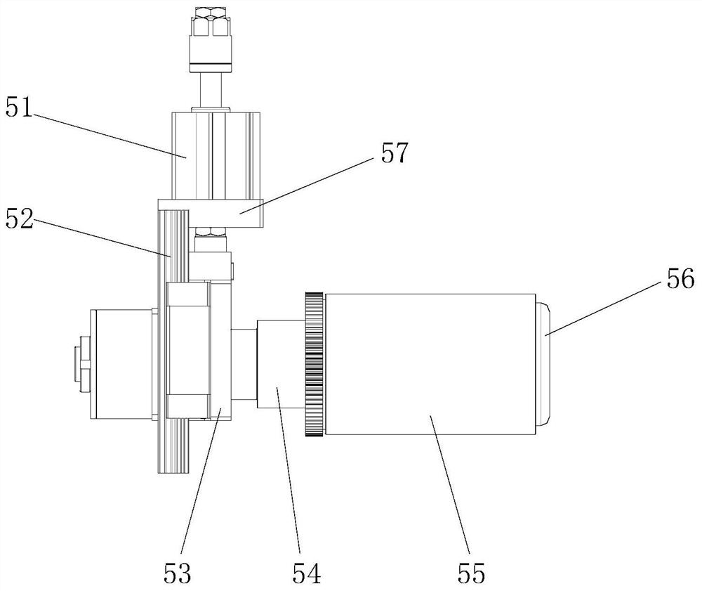
[0062] By adopting the above-mentioned technical scheme, when the conveying resistance of the steel strip is large, the first lifting cylinder 51 drives the first main shaft 54 ​​to descend so that the gears on it mesh with the gears on the feeding drive roller 6 or the second lifting cylinder 91 drives The second main shaft 94 descends to make the gear on it mesh with the gear on the blanking driving roller 10, and the first main shaft 54 ​​is driven to rotate by the feeding driving roller 6 or the second main shaft 94 is driven by the blanking driving roller 10 to rotate, so that the steel The conveying of the belt is more stable.

[0063] Among the present invention, the ultrasonic sensor 3 selects the DS-UE28R type of Dong...


PUM


Abstract

The invention discloses steel belt feeding and discharging equipment which comprises a feeding machine and a discharging machine. The feeding machine comprises a feeding machine rack; an air expansionshaft is arranged on the feeding machine rack; an ultrasonic sensor is arranged at the position, located at the upper left corner of the air expansion shaft, on the feeding machine rack; a photoelectric sensor is arranged on one side of the ultrasonic sensor; a feeding driving roller is arranged on one side of the photoelectric sensor; a lifting roller lifting mechanism is arranged above the feeding driving roller; a swing roller mechanism is arranged at the lower left corner of the feeding driving roller; a plurality of carrier rollers are further arranged on the feeding machine rack; the discharging machine comprises a discharging machine rack; and a discharging driving roller is arranged on the discharging machine rack. The invention further discloses an implementation method of the steel belt feeding and discharging equipment. According to the steel belt feeding and discharging equipment and the implementation method thereof provided by the invention, the lifting roller lifting mechanism and a heating roller lifting mechanism are arranged, and the height of a lifting roller and the height of a heating roller can be adjusted conveniently, so that the tension degree of a steel belt can be adjusted conveniently, the stability in conveying steel materials is achieved, and the steel belt is prevented from being broken.

Description

technical field [0001] The invention belongs to the technical field of steel strip loading and unloading, and in particular relates to a steel strip loading and unloading device and a realization method thereof. Background technique [0002] At present, the customer's factory requires rolling treatment of the steel strip at high temperature, so that the steel strip can obtain the corresponding inductance performance. This process involves high temperature treatment, which is not convenient for manual direct production. And it is required that the steel strip does not break during the production process, and the obtained performance needs to meet the requirements of the factory. Therefore, the loading and unloading equipment needs to be carried out smoothly without excessive swings. [0003] There are some problems in the existing steel belt loading and unloading mechanism during use. For example, the position of the steel belt cannot be adjusted, and the steel belt is pron...

Claims


Application Information

Patent Timeline
Patent Type & Authority Applications(China)
IPC IPC(8): B65H23/26B65H23/038B65H23/34B65H26/00
CPCB65H23/26B65H23/038B65H23/34B65H26/00
Inventor 何晶锋刘晋胡意周
Owner 东阳东磁自动化科技有限公司
Why Eureka
Try Eureka