Wall perforating device for indoor decoration

A drilling device and interior decoration technology, which is applied to stone processing tools, work accessories, manufacturing tools, etc., can solve the problems of debris splashing, height adjustment, etc., and achieve the effect of saving energy, reducing work intensity, and facilitating drilling

Inactive Publication Date: 2021-04-02
龙三妹
View PDF1 Cites 1 Cited by
  • Summary
  • Abstract
  • Description
  • Claims
  • Application Information

AI Technical Summary

Problems solved by technology

[0005] In order to overcome the disadvantages that manual drilling is required when the wall is punched, so that debris splashes everywhere and the height cannot be adjusted, the technical problem of the present invention is: to provide a wall drilling machine for interior decoration that automatically punches holes, adjusts up and down, and collects debris. hole device

Method used


Image

  • Wall perforating device for indoor decoration
  • Wall perforating device for indoor decoration
  • Wall perforating device for indoor decoration

Examples


Embodiment 1

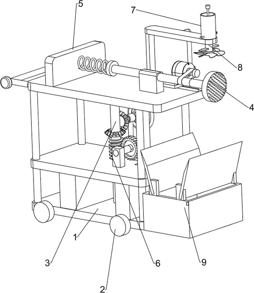
[0029] A wall punching device for interior decoration, such as Figure 1-Figure 3 As shown, it includes base plate 1, wheel 2, first support column 3, punching mechanism 4 and extruding mechanism 5, base plate 1 is provided with wheels 2 around, and the middle rotation type is provided with first support column 3 on base plate 1, base plate 1 is provided with a punching mechanism 4, and the left side of the punching mechanism 4 is provided with an extruding mechanism 5.

[0030] When it is necessary to use this equipment to punch holes, the extrusion mechanism 5 is manually pushed, and the extrusion mechanism 5 drives the wheels 2 to move to the wall, and then squeezes the punching mechanism 4 to punch holes on the wall. After the wall is punched, Manually pull the extruding mechanism 5 to move backward, so that the punching mechanism 4 leaves the wall and no longer punches holes. If the wall needs to be punched, the above steps are repeated.

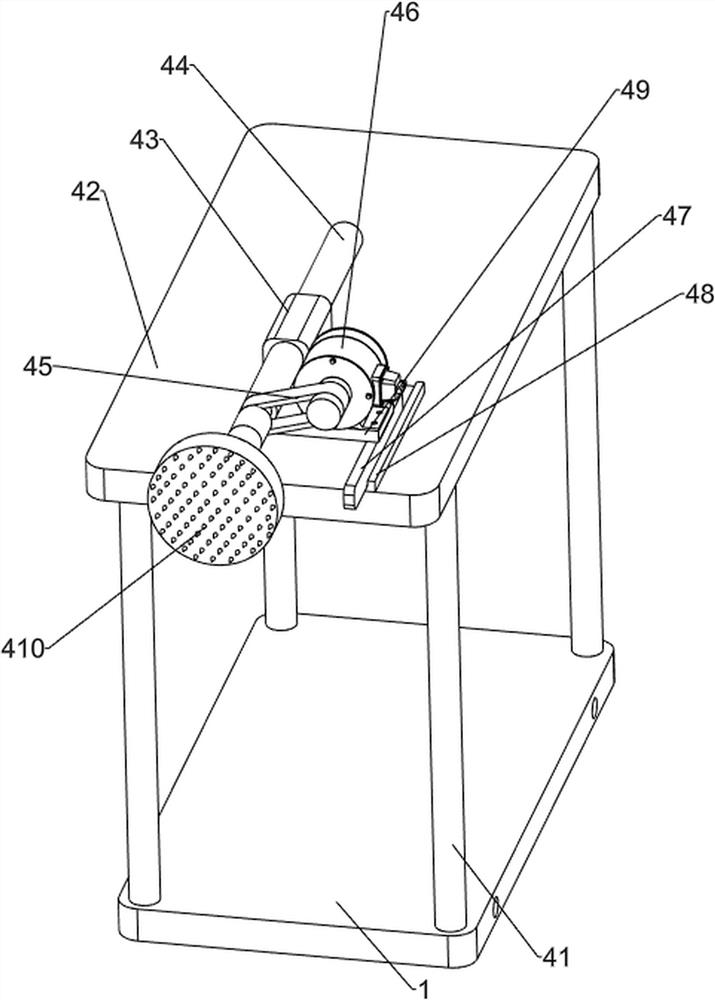
[0031] The punching mechanism 4...

Embodiment 2

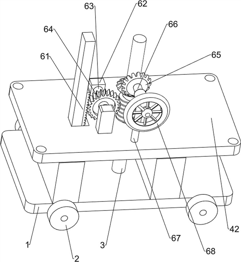
[0036] On the basis of Example 1, such as figure 1 , Figure 4-Figure 7 Shown, also comprise up and down mechanism 6, and up and down mechanism 6 comprises rack 61, the 3rd fixed post 62, the first rotating shaft 63, spur gear 64, bevel gear set 65, the second rotating shaft 66, the 4th fixed post 67 and the rotating disc 68, the right side of the middle panel 42 is provided with a rack 61, the panel 42 middle part is provided with a third fixed post 62, and the third fixed post 62 is provided with a first rotating shaft 63 for rotation. , the middle part of the first rotating shaft 63 is provided with a spur gear 64, the spur gear 64 meshes with the rack 61, the upper rear part of the panel 42 is provided with a fourth fixed post 67, and the fourth fixed post 67 is rotatably provided with a second rotating shaft 66 A bevel gear set 65 is provided between the front side of the second rotating shaft 66 and the first support column 3 , and a rotating disk 68 is provided at the ...


PUM


Abstract

The invention relates to a perforating device, in particular to a wall perforating device for indoor decoration. The wall perforating device for indoor decoration is capable of automatically conducting perforating and adjusting up and down and collecting residual chips. The wall perforating device for indoor decoration comprises a bottom plate, wheels, a first supporting column, a perforating mechanism, an extruding mechanism and the like. The wheels are arranged around the bottom plate, the first supporting column is rotationally arranged in the middle of the bottom plate, the perforating mechanism is arranged on the bottom plate, and the extruding mechanism is arranged on the left side of the perforating mechanism. The perforating mechanism is arranged, thus the wall perforating device is manually pushed to the wall surface, a motor is started, a transmission assembly rotates to drive a drill bit to rotate, then the wall perforating device is slowly pushed, the drill bit rotates to perforate the wall surface, and the effects of automatic perforating, reduction the working intensity of workers and improvement of the working efficiency are achieved. The perforating mechanism and the extruding mechanism are matched with each other, when a push rod pushes the drill bit to conduct perforating, a first sliding column slides backwards, and therefore a spring is extruded.

Description

technical field [0001] The invention relates to a punching device, in particular to a wall punching device for indoor decoration. Background technique [0002] When the interior decoration wall is pierced, it is necessary to use an electric drill to turn the hole. When using the electric drill to turn the hole, it is necessary to manually pick up the electric drill to face the wall. Filling and re-drilling is not only troublesome but also easily affects the appearance of the wall. The debris that appears during drilling is splashed everywhere, affecting the staff. [0003] Patent application: CN201922238191.6, the publication date is 20191213, which discloses a convenient and labor-saving wall punching device, including a bottom plate, a lifting platform, a box body, a first motor, a first gear, an internally threaded sleeve, and a second gear , chain, screw, motor box, second motor, drill bit and other parts, the lifting table is fixedly installed on the top of the bottom ...

Claims


Application Information

Patent Timeline
Patent Type & Authority Applications(China)
IPC IPC(8): B28D1/14B28D7/00B28D7/02
CPCB28D1/146B28D7/00B28D7/02
Inventor 龙三妹
Owner 龙三妹
Why Eureka
Try Eureka