
Diamond edge accurate auxiliary grinding and polishing equipment

An edge and precise technology, applied in grinding/polishing equipment, grinding/polishing safety devices, metal processing equipment, etc., can solve the problems of easy hand injury and close proximity of hands to the grinding machine, so as to prevent dust splash and save manpower , prevent the effect of overheating

Active Publication Date: 2021-04-02
江西欣和光电有限公司
View PDF7 Cites 2 Cited by
  • Summary
  • Abstract
  • Description
  • Claims
  • Application Information

AI Technical Summary

Problems solved by technology

[0002] The culture of diamonds has a long history, and some people regard it as a symbol of love and loyalty. After the diamonds are produced, their edges need to be polished to make them smoother and more beautiful. At present, diamonds are hand-held manually to fit the edges of the diamonds. Grinding machine can be used to polish it, but this method is relatively close to the grinding machine, which has certain dangers. The diamond has high hardness and has relatively sharp parts, and it is easy to hurt hands when holding it for grinding.

Method used


Image

  • Diamond edge accurate auxiliary grinding and polishing equipment
  • Diamond edge accurate auxiliary grinding and polishing equipment
  • Diamond edge accurate auxiliary grinding and polishing equipment

Examples


Embodiment 1

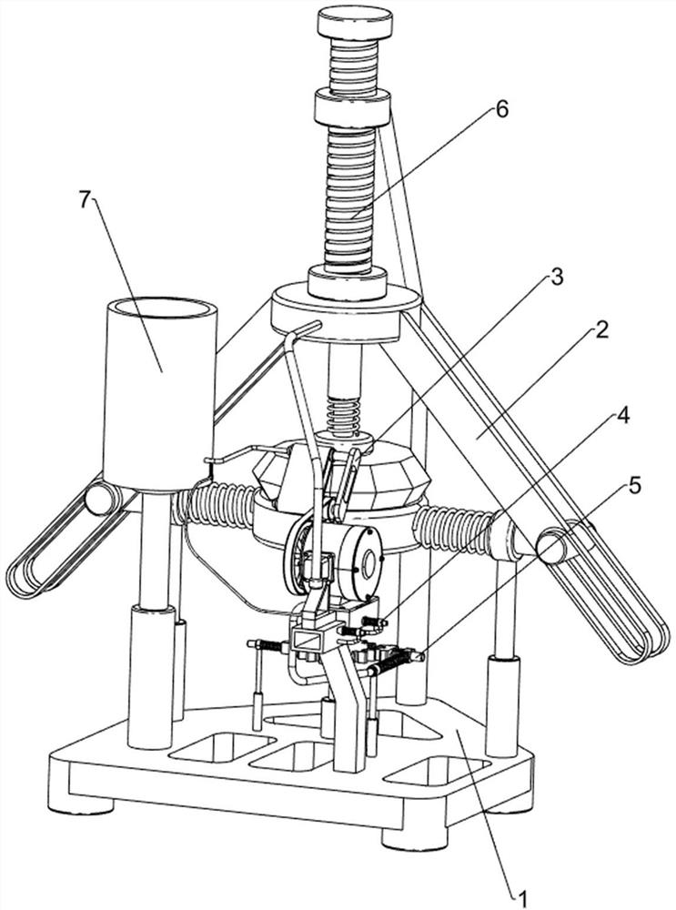
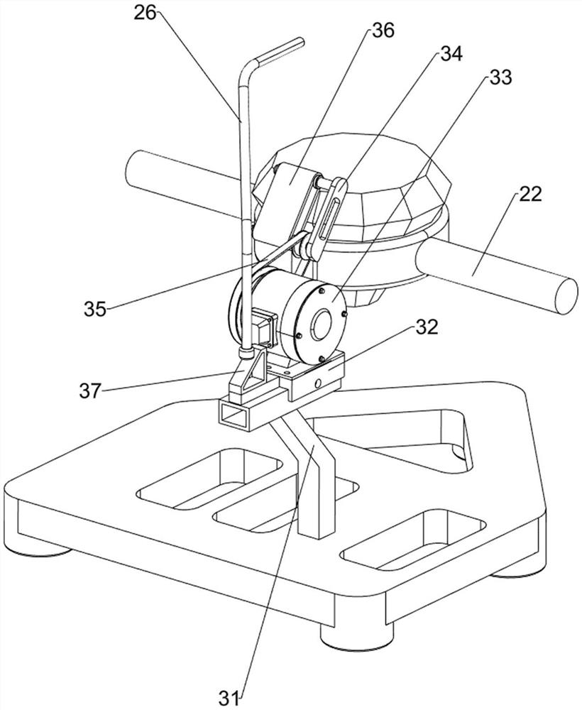
[0060] A diamond edge precise auxiliary grinding and polishing equipment, such as figure 1 As shown, it includes a base 1 , a clamping mechanism 2 and a grinding mechanism 3 , the clamping mechanism 2 is provided in the middle of the top of the base 1 , and the grinding mechanism 3 is provided on the front side of the top of the base 1 .

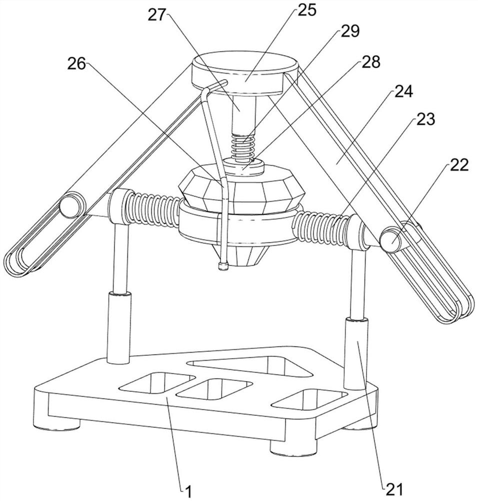
[0061] like figure 2 As shown, the clamping mechanism 2 includes a first guide sleeve 21, a clamping rod 22, a first spring 23, a guide rod 24, a sliding plate 25, a first push rod 26, a second guide sleeve 27, a pressing block 28 and a second Spring 29, the first guide sleeve 21 is symmetrically arranged in the middle of the top of the base 1, and the first guide sleeve 21 is provided with a sliding rod 22, and the first spring 23 is connected between the clamp rod 22 and the first guide sleeve 21 , the guide rods 24 are slidingly arranged on the clamping rods 22, and a sliding plate 25 is connected between the tops of the guiding rods 24...

Embodiment 2

[0065] On the basis of Example 1, such as Figure 4 As shown, a positioning mechanism 4 is also included, and the positioning mechanism 4 includes a first sliding sleeve 41, a positioning rod 42 and a third spring 43. The first mounting column 31 is symmetrically provided with the first sliding sleeve 41 front and back, and the first sliding sleeve A positioning rod 42 is slidably arranged inside the sleeve 41 , and a third spring 43 is connected between the positioning rod 42 and the first sliding sleeve 41 .

[0066] When the slide plate 32 moves backward, the front positioning rod 42 moves to the right, and the third spring 43 on the front side is compressed. The front positioning rod 42 moves to the left and resets. When the slide plate 32 moves backward and contacts the rear positioning rod 42, the rear positioning rod 42 is moved to the right, and the third rear spring 43 is compressed. When the sliding plate 32 moves backward When it can cooperate with the rear side po...


PUM


Abstract

The invention relates to polishing equipment, in particular to diamond edge accurate auxiliary grinding and polishing equipment. Through the diamond edge accurate auxiliary grinding and polishing equipment, grinding work can be conducted without holding a diamond manually. According to the technical scheme, the diamond edge accurate auxiliary grinding and polishing equipment comprises a base and agrinding mechanism, wherein a clamping mechanism is arranged in the middle of the top of the base; and the grinding mechanism is arranged on one side of the top of the base. According to the equipment, the to-be-ground diamond can be clamped through the arranged clamping mechanism, and then the diamond can be ground through the grinding mechanism; and the position of a sliding plate can be limited through an arranged locating mechanism.

Description

technical field [0001] The invention relates to a polishing device, in particular to a diamond edge precise auxiliary grinding and polishing device. Background technique [0002] The culture of diamonds has a long history, and some people regard it as a symbol of love and loyalty. After the diamonds are produced, their edges need to be polished to make them smoother and more beautiful. At present, diamonds are hand-held manually, and the edges of the diamonds are pasted together. Grinding machine can be used to polish it, but this method is relatively close to the grinding machine, which has certain dangers. The diamond has high hardness and has relatively sharp parts, and it is easy to hurt hands when holding it for grinding. [0003] Therefore need to design a kind of diamond edge accurate auxiliary grinding and polishing equipment that just can carry out grinding work without manual hand-held diamond. Contents of the invention [0004] In order to overcome the disadvan...

Claims


Application Information

Patent Timeline
Patent Type & Authority Applications(China)
IPC IPC(8): B24B21/00B24B21/18B24B41/06B24B47/00B24B47/12B24B47/22B24B55/02B24B55/08
CPCB24B21/002B24B21/18B24B41/06B24B47/00B24B47/12B24B47/22B24B55/02B24B55/08
Inventor 李錾
Owner 江西欣和光电有限公司
Learn More