
A wire tail fixer

A fixer and wire tail technology, which is applied in the field of wire tail fixators, can solve the problems of inconvenience in carrying, easy damage to wires, and reduced work efficiency, and achieves the effects of quick and convenient installation, beautiful appearance, and easy portability.

Active Publication Date: 2022-05-13
GUANGDONG POWER GRID CO LTD +1
View PDF0 Cites 0 Cited by
  • Summary
  • Abstract
  • Description
  • Claims
  • Application Information

AI Technical Summary

Problems solved by technology

[0002] In low-voltage lines, the common method of fixing wire tails is to fix them with wires. When only wires are used for fixing, the wires are easily damaged. The existing wire tail fixing devices need to be fixed by screws, and external Different types of installation tools are required to fix wire tails of different wire diameters. Different types of fixing devices are required, which leads to the need for staff to carry various types of fixing devices when working, which is inconvenient to carry and reduces work efficiency.

Method used


Image

  • A wire tail fixer
  • A wire tail fixer
  • A wire tail fixer

Examples


Embodiment 1

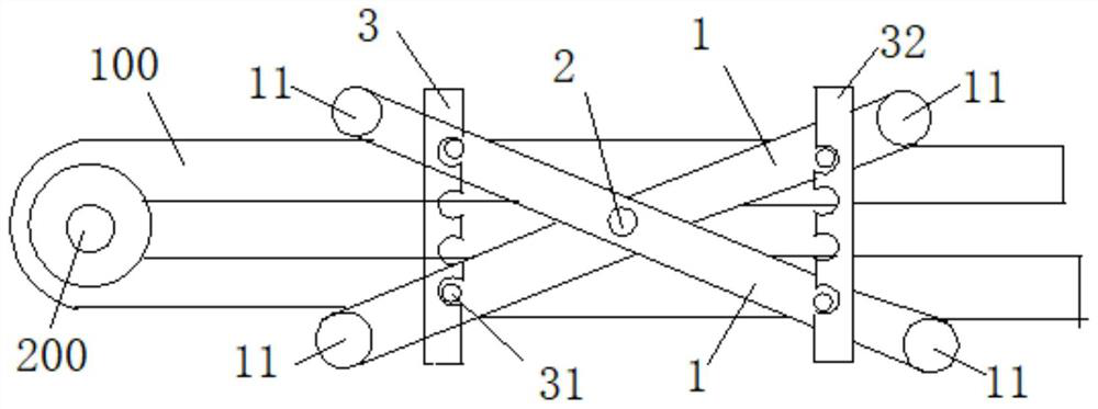
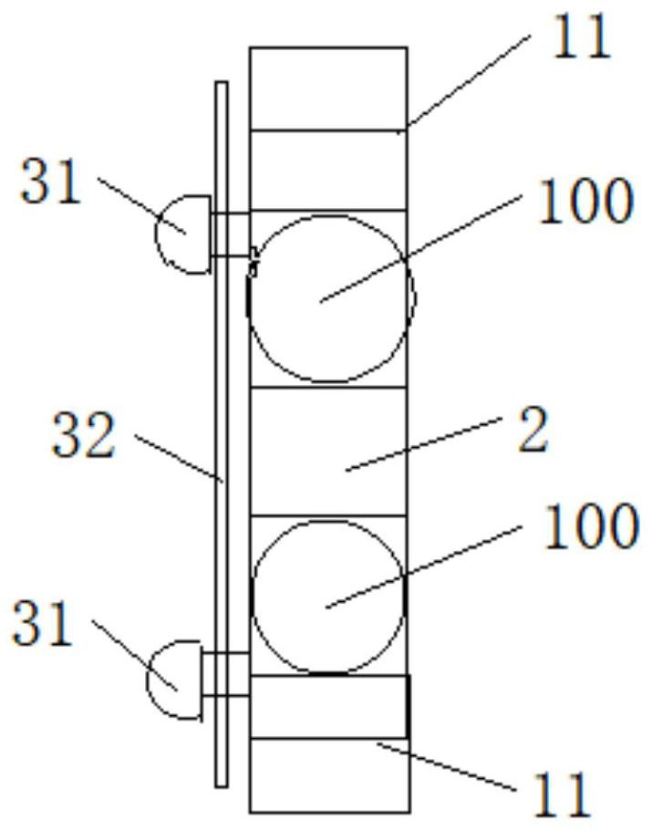
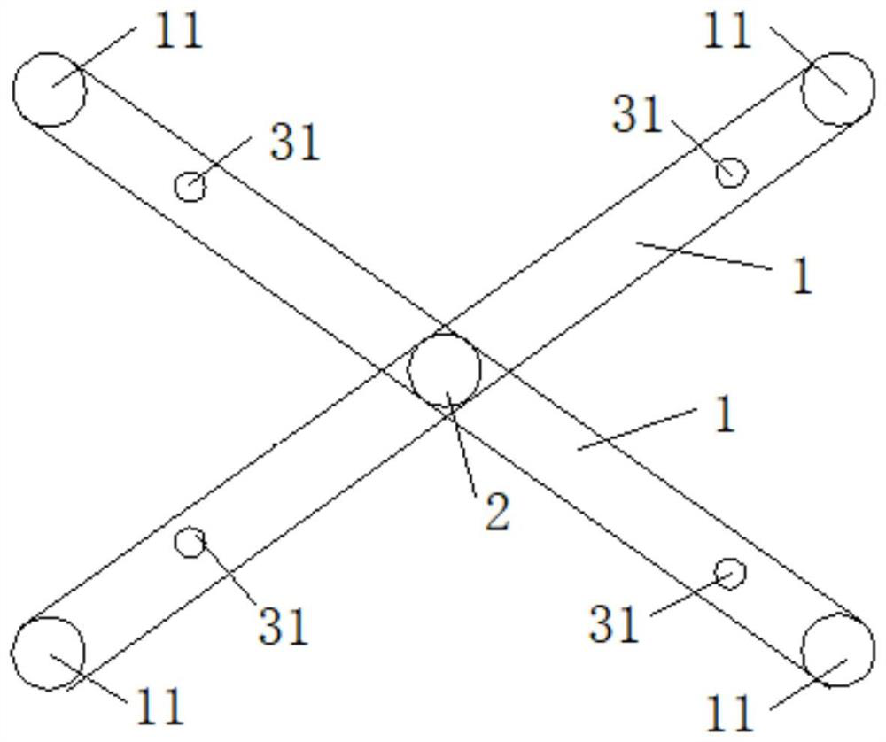
[0033] Such as Figure 1-Figure 4 As shown, the present invention provides a wire tail fixer, which includes two brackets 1, a connecting shaft 2 and a locking mechanism 3, the two brackets 1 are arranged crosswise, and the two ends of the bracket 1 are respectively provided with an anti-damage wire fixing shaft 11; The connecting shaft 2 is arranged at the intersection of the two brackets 1, and the two brackets 1 are connected through the rotation of the connecting shaft 2. One end of the connecting shaft 2 protrudes relative to the two brackets 1, and the two brackets 1 can clamp the wire 100 when they rotate. The locking mechanism 3 can lock the two brackets 1 when the wire 100 is interposed between the fixed shaft 11 and the connecting shaft 2 of the anti-injury line.

[0034] In this embodiment, the wire end fixer is made of high-strength steel and painted material, and adopts a sliding surface design. Two brackets 1 are symmetrically arranged in an X-shaped structure, a...

Embodiment 2

[0043] The thread tail retainer provided by the embodiment of the present invention has the same support 1 , the wound-proof thread fixing shaft 11 , the connecting shaft 2 , the bolt fixing column 31 and the multi-hole bolt 32 as those in the first embodiment. The difference between this embodiment and Embodiment 1 is that the anti-slip effect of the anti-injury line fixed shaft 11 is further enhanced, the friction between the wire 100 and the anti-injury line fixed shaft 11 is increased, and the wire 100 is prevented from moving along the anti-injury line fixed shaft 11 Axial slippage.

[0044] Optionally, an insulating rubber layer is provided on the surface of the anti-injury line fixing shaft 11, which not only increases the friction between the anti-injury line fixing shaft 11 and the wire 100, does not damage the wire 100, but also strengthens the connection between the wire 100 and the wire tail fixer. insulation effect. In addition, anti-slip protrusions can also be ...


PUM


Abstract

The invention belongs to the technical field of electric power equipment, and discloses a line tail fixer, which includes two brackets, a connecting shaft and a locking mechanism, the two brackets are arranged crosswise, and the two ends of the bracket are respectively provided with an anti-damage line fixing shaft; the connecting shaft is provided with At the intersection of the two brackets, the two brackets are rotatably connected by a connecting shaft. One end of the connecting shaft protrudes relative to the two brackets. When the two brackets rotate, the wire can be sandwiched between the fixed shaft of the anti-injury line and the connecting shaft. between; when the wire is sandwiched between the fixed shaft and the connecting shaft of the anti-injury line, the locking mechanism can lock the two brackets. The two brackets of the wire tail fixer of the present invention are connected in an X-shaped structure. When the locking mechanism locks the two brackets, the wire tail is clamped and fixed between the anti-damage wire fixing shaft and the connecting shaft, and no screws are needed for fixing or using. It is suitable for wires of various wire diameters. It is quick and convenient to install, can effectively reduce the risk of wire damage, and is easy to carry around.

Description

technical field [0001] The invention relates to the technical field of electric equipment, in particular to a wire tail fixer. Background technique [0002] In low-voltage lines, the common method of fixing wire tails is to fix them with wires. When only wires are used for fixing, the wires are easily damaged. The existing wire tail fixing devices need to be fixed by screws, and external Different types of fixing devices are required to fix wire tails of different wire diameters. As a result, workers need to carry multiple types of fixing devices when working, which is inconvenient to carry and reduces work efficiency. Contents of the invention [0003] The purpose of the present invention is to provide a wire tail fixer, which does not need to be fixed by screws or other auxiliary tools for installation, is suitable for wires of various wire diameters, is quick and convenient to install, has a beautiful appearance, and can effectively reduce the risk of wire being damaged...

Claims


Application Information

Patent Timeline
Patent Type & Authority Patents(China)
IPC IPC(8): H02G7/05
CPCH02G7/05
Inventor 凌福强陈德新黄欣游畅炎陈育辉温秋灵谢丙辉谭小霖罗通宏何南鸿
Owner GUANGDONG POWER GRID CO LTD
Learn More