BIM-based rail transit tunnel clearance checking method and system

A rail transit and tunnel technology, applied in the field of BIM model (Building Information Modeling), can solve the problems of scanning angle interval, waste of human resources and material resources, and inability to achieve accurate measurement, so as to prevent safety accidents, ensure safety, and maintain a good The effect of use effect and economic benefit

Pending Publication Date: 2021-03-30
CHINA RAILWAY SIYUAN SURVEY & DESIGN GRP
View PDF0 Cites 0 Cited by
  • Summary
  • Abstract
  • Description
  • Claims
  • Application Information

AI Technical Summary

Problems solved by technology

The limitation of the cross-section detection method is that the running speed of the detection vehicle is required to be very low during the detection process, and the influence of the vibration offset of the train under the high-speed running state cannot be detected
When an over-limit situation occurs, it is necessary to immediately stop and reverse the car and repeat it many times, manually marking the over-limit situation, wasting too many human and material resources
The disadvantage of the laser radar detection method is that firstly, the laser radar itself has a system error of about 15mm, which cannot meet the requirements of accurate measurement;
Finally, the lidar adopts the principle of multi-pulse echo ranging, and the scanning frequency is generally around 50HZ, which is not suitable for high-speed and real-time detection requirements.
Due to the sudden characteristics of limit changes and the lack of efficient maintenance methods in the current limit detection and calibration, the development of a real-time, high-speed, high-precision limit calibration method will help save labor, Reduce expenses, improve efficiency, provide a basis for the safety maintenance of urban rail transit, and improve the safety of subway operation

Method used


Image

  • BIM-based rail transit tunnel clearance checking method and system
  • BIM-based rail transit tunnel clearance checking method and system

Examples


Embodiment Construction

[0043] In order to make the object, technical solution and advantages of the present invention clearer, the present invention will be further described in detail below in conjunction with the accompanying drawings and embodiments. It should be understood that the specific embodiments described here are only used to explain the present invention, not to limit the present invention. In addition, the technical features involved in the various embodiments of the present invention described below can be combined with each other as long as they do not constitute a conflict with each other.

[0044] It should be noted that, in the functional equations involved in the present invention, the symbol "·" is an operation symbol representing the multiplication of two constants or vectors before and after, and " / " is an operation symbol representing the division of two constants or vectors before and after. In the present invention All functional equations follow the mathematical rules of a...


PUM


Abstract

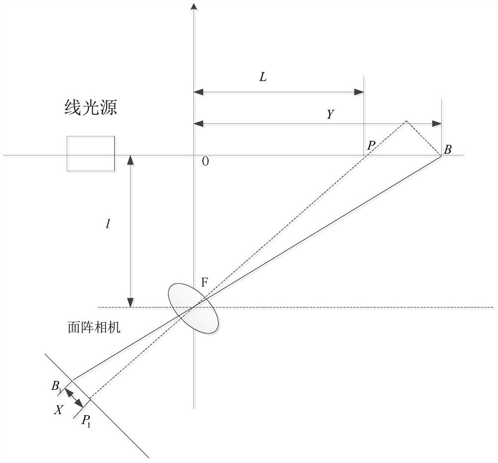
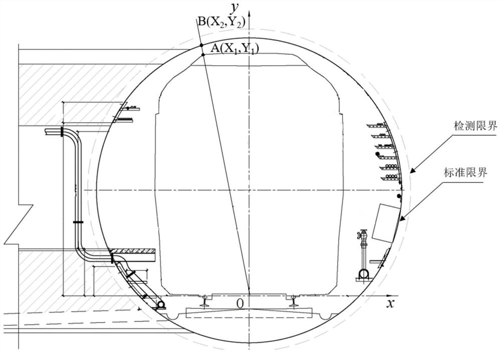
The invention provides a BIM-based rail transit tunnel clearance checking method, which comprises the steps of obtaining a two-dimensional image of at least one target clearance area in a tunnel, detecting an actual distance of a current target clearance area according to a triangulation ranging technology, and obtaining a detection clearance model; extracting a standard clearance area corresponding to the target clearance area, and establishing a standard clearance model according to a BIM technology; and respectively extracting the detection clearance and the standard clearance in the same direction from the detection clearance model and the standard clearance model, and converting the distance between the detection clearance and the standard clearance in the same coordinate system so asto judge whether clearance invasion exists in the tunnel in the direction or not. The clearance is detected through the triangulation ranging technology, so that field clearance data can be accurately acquired in real time; and the clearance data obtained by detection is compared and calculated with the standard clearance model established in the BIM model and is compared with a safety gap value,so that the real-time checking of the clearance data is realized, and the clearance invasion position can be timely and accurately judged.

Description

technical field [0001] The invention belongs to the field of rail transit boundary detection, and in particular relates to a rail transit tunnel boundary checking method and system based on a BIM model (Building Information Model; English abbreviation of Building Information Modeling). Background technique [0002] In the existing technology, the underground working environment of rail transit is often relatively harsh. Vibration of vehicles, looseness of building firmware, thermal expansion and contraction will all lead to deformation of buildings, equipment, and pipelines. Potential safety hazards, timely renovation. When an object invades the equipment limit, the subway vehicle will not be able to operate normally, and in severe cases, it will cause an operation accident. [0003] At present, in the equipment limit detection, the method used is mainly the static detection method. Including section detection method and lidar detection method. The limitation of the cross...

Claims


Application Information

Patent Timeline
IPC IPC(8): G01S17/48G06T5/00G06T7/70
CPCG01S17/48G06T7/70G06T5/70
Inventor 代刚肖潜飞李文胜周小斌史明红姚应峰刘奥范永光胡立翔邱海波朱昊天陈东喻岚
Owner CHINA RAILWAY SIYUAN SURVEY & DESIGN GRP
Why Eureka
Try Eureka