Drying device for non-woven fabric production

A drying device, non-woven technology, applied in drying, dryer, progressive dryer and other directions, can solve the problems of long time and low drying efficiency, and achieve the effect of avoiding wrinkles

Active Publication Date: 2021-03-30
ZHENGZHOU TEXTILE MACHINERY AUTOMATIC CONTROL EQUIP
View PDF5 Cites 4 Cited by
  • Summary
  • Abstract
  • Description
  • Claims
  • Application Information

AI Technical Summary

Problems solved by technology

[0002] In the drying process of non-woven fabric production, since the non-woven fabric contains

Method used


Image

  • Drying device for non-woven fabric production
  • Drying device for non-woven fabric production
  • Drying device for non-woven fabric production

Examples


Embodiment 1

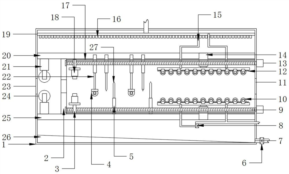
[0020] see Figure 1-4 , a drying device for non-woven fabric production, comprising a drying box 1 and a drying structure, the inside of the drying box 1 is provided with a drying structure, and the drying structure includes an inlet 23, a cloth outlet 11 , cloth clamping and guiding structure, inlet water squeezing structure, intermediate water squeezing structure, end drying structure and winding structure, the two sides of the drying box 1 are respectively provided with an inlet 23 and a cloth outlet 11, and the inlet The side of the mouth 23 is provided with an entrance water squeezing structure, and the side of the entrance water squeezing structure is provided with a cloth clamping and guiding structure. An end drying structure is arranged on the side, and a winding structure is arranged on the side of the cloth outlet 11 . First, the cloth enters from the inlet 23, and then the cloth is clamped and moved laterally by the cloth clamping and guiding structure, so that t...

Embodiment 2

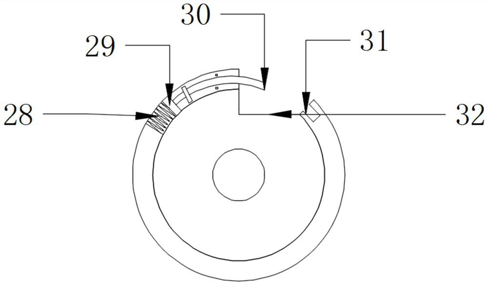
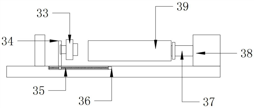
[0027] Compared with Embodiment 1, the improvement of this embodiment is that: the winding roller 39 is provided with an end clamping structure, and the end clamping structure includes a clamping spring 28, a clamping slider 29, an electromagnetic Clamping bolt 30, magnetic clamping groove 31 and clamping groove 32, described winding roller 39 side offers clamping groove 32, and described clamping groove 32 side offers magnetic clamping groove 31, and described clamping groove 32 The other end is provided with a sliding groove, and the inside of the sliding groove is slidably provided with a clamping slider 29, the end of the clamping slider 29 is fixed with a clamping spring 28, and the other end of the clamping slider 29 is provided with an electromagnetic card. The locking bolt 30 , the electromagnetic locking bolt 30 is matched with the locking groove 32 . First, the end of the non-woven fabric is placed inside the clamping groove 32, and then the magnetism of the electrom...


PUM


Abstract

The invention discloses a drying device for non-woven fabric production. The drying device for non-woven fabric production comprises a drying box body and a drying structure, and the drying structurecomprises an inlet, a cloth outlet, a cloth clamping and guiding structure, an inlet water squeezing structure, a middle water squeezing structure, an end drying structure and a winding structure. Themiddle water squeezing structure comprises a middle roller, a bottom telescopic rod, a scraping plate, a middle telescopic rod and an upper telescopic rod. According to the the device, through the arrangement of the water squeezing structure, waste water on a non-woven fabric is squeezed out firstly in the drying process, so that the drying efficiency is improved. The clamping guide structure isarranged on the device, so that the end part of the non-woven fabric can be automatically guided, the non-woven fabric can be automatically pulled to the position of the cloth outlet, and inconvenience caused by manual feeding is avoided. The device is provided with a communicating roll and a communicating nozzle, so that the cloth can be flattened and dried at the same time, and wrinkles are avoided.

Description

technical field [0001] The invention relates to a drying device, in particular to a drying device for non-woven fabric production. Background technique [0002] In the drying process of non-woven fabric production, since the non-woven fabric contains water, it takes a long time to simply pass hot air to dry it, and the drying efficiency is low. Contents of the invention [0003] The object of the present invention is to provide a drying device for non-woven fabric production to solve the problems raised in the above-mentioned background technology. [0004] To achieve the above object, the present invention provides the following technical solutions: [0005] A drying device for non-woven fabric production, comprising a drying box and a drying structure, the drying box is provided with a drying structure inside, and the drying structure includes an inlet, a cloth outlet, and a cloth clamping guide Structure, inlet water squeeze structure, middle water squeeze structure, ...

Claims


Application Information

Patent Timeline
IPC IPC(8): F26B13/12F26B13/28F26B25/00D06C15/00
CPCF26B13/12F26B13/28F26B25/003D06C15/00Y02P70/10
Inventor 熊小玲
Owner ZHENGZHOU TEXTILE MACHINERY AUTOMATIC CONTROL EQUIP
Why Eureka
Try Eureka