
Electronic expansion valve

A technology of electronic expansion valve and valve seat, which is applied in the direction of lift valve, valve details, valve device, etc., which can solve the problems of low coaxiality and so on.

Active Publication Date: 2021-03-30
ZHEJIANG DUNAN HETIAN METAL CO LTD
View PDF5 Cites 2 Cited by
  • Summary
  • Abstract
  • Description
  • Claims
  • Application Information

AI Technical Summary

Problems solved by technology

[0005] The invention provides an electronic expansion valve to solve the problem of low coaxiality in the prior art

Method used


Image

  • Electronic expansion valve
  • Electronic expansion valve
  • Electronic expansion valve

Examples


Embodiment 1

[0049] The assembly steps of the device provided in Embodiment 1 are:

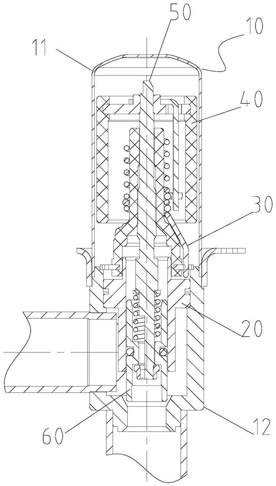
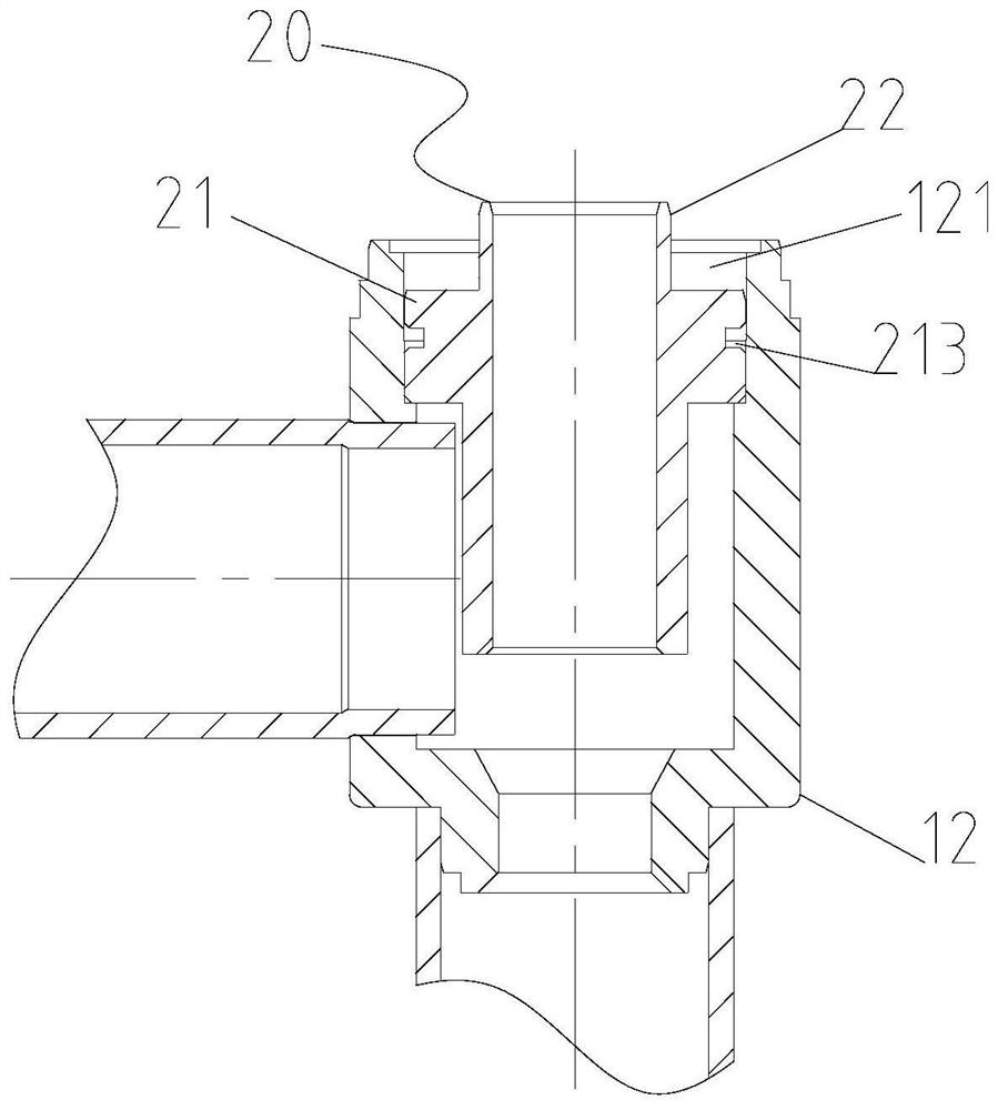
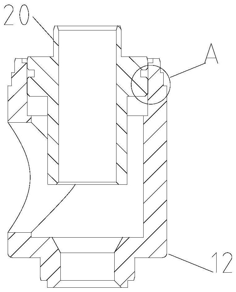
[0050] (1) Put the guide sleeve 20 into the valve seat 12, the fourth section 212 of the guide sleeve 20 is in clearance fit with the first section 121a of the valve seat 12, so that the guide sleeve 20 can be positioned and guided;

[0051] (2) Press-fit the guide sleeve 20 so that the lower surface of the installation boss 21 is in contact with the stepped surface of the limiting boss 121c, and the fourth section 212 of the guide sleeve 20 is closely matched with the second section 121b of the valve seat 12 . At this time, there is a gap of 0.01mm to 0.04mm on one side between the third section 211 of the guide sleeve 20 and the first section 121a of the valve seat 12 as a welding seam, and a welding ring is placed in the welding ring groove 213;

[0052] (3) Assemble the first pipe fitting and the second pipe fitting on the valve seat 12 , and weld the first pipe fitting, the second pipe fitting, the gu...


PUM


Abstract

The invention provides an electronic expansion valve. The electronic expansion valve comprises a shell, a guide sleeve, a rotor, a screw rod and a valve needle assembly; the guide sleeve is arranged in the shell; the rotor is rotatably arranged in the shell; the screw rod is arranged in the shell, and the rotor is in driving connection with the screw rod; the valve needle assembly is movably arranged in the shell, and one end of the screw rod is connected with the valve needle assembly so as to drive the valve needle assembly to move axially through the screw rod; and a guide section and a press-fitting section which communicate with each other are arranged between the inner wall of the shell and the outer wall of the guide sleeve, the distance between the guide sleeve located on the guidesection and the shell is larger than the distance between the guide sleeve located on the press-fitting section and the shell, a welding ring groove is further formed between the inner wall of the shell and the outer wall of the guide sleeve, and the welding ring groove communicates with the guide section. Through the technical scheme provided by the invention, the problem of low coaxiality in the prior art can be solved.

Description

technical field [0001] The present invention relates to the technical field of electronic expansion valves, in particular to an electronic expansion valve. Background technique [0002] At present, the electronic expansion valve includes a housing and a guide sleeve, and the guide sleeve is arranged in the housing. Wherein, the electronic expansion valve is respectively connected with the first pipe member and the second pipe member, and the electronic expansion valve can be used to control the communication between the first pipe member and the second pipe member. [0003] When assembling the electronic expansion valve with the first pipe fitting and the second pipe fitting, the first pipe fitting and the second pipe fitting are first welded to the housing by furnace welding, and then the guide sleeve is press-fitted into the housing, because the guide sleeve The existing structure of the shell and the shell cannot meet the welding process requirements of the furnace weldi...

Claims


Application Information

Patent Timeline
IPC IPC(8): F16K1/38F16K1/32F16K27/02F16K1/42F25B41/31
CPCF16K1/38F16K1/32F16K27/0254F16K1/42
Inventor 詹少军邸志强程明扬
Owner ZHEJIANG DUNAN HETIAN METAL CO LTD
Learn More