Residue filtering basket of water tank drainer
A technology for filtering residues and sinks, applied in the field of kitchen utensils, can solve the problems of difficult cleaning, easy retention of dirt, deep depth, etc., and achieve the effect of simple structure
- Summary
- Abstract
- Description
- Claims
- Application Information
AI Technical Summary
Problems solved by technology
Method used
Image
Examples
Embodiment 1
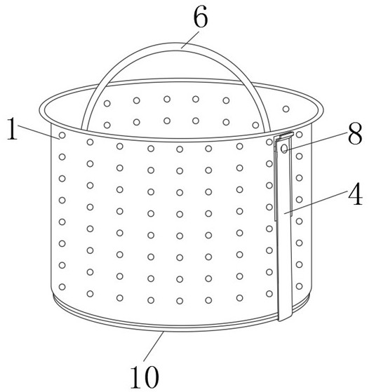
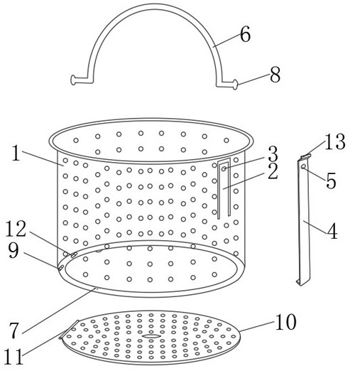
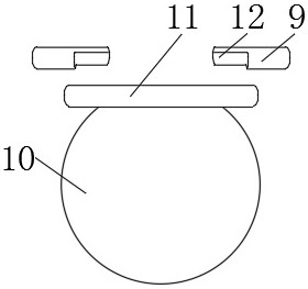
[0019] Embodiment one, by figure 1 , figure 2 with image 3 Given, the present invention includes a basket body 1, one side of the basket body 1 is provided with a positioning piece 2, the surface of the positioning piece 2 is provided with a first fixing hole 3, and the outer side of the positioning piece 2 is fixedly connected with a locking card 4, and the locking card 4 The upper surface of the upper part of the basket is provided with a second fixing hole 5, and a lifting ring 6 is installed on the upper edge of the basket body 1. One end of the lifting ring 6 is connected to the basket body 1, and the other end of the lifting ring 6 passes through the first fixing hole 3 and the second fixing hole in turn. Two fixing holes 5, the outer sides of both ends of the lifting ring 6 are provided with a first limit stop 8, the bottom edge of the basket body 1 is provided with a shaft sleeve 9, and the bottom of the basket body 1 is equipped with a movable bottom cover 10, the ...
Embodiment 2
[0020] Embodiment two, on the basis of embodiment one, by figure 1 with figure 2 Given, the side wall of the basket body 1 and the surface of the movable bottom cover 10 are provided with water holes, which is convenient for leaching out the waste water in the filter residue basket, so as to avoid too much water and dirty the kitchen when disposing of kitchen waste.
Embodiment 3
[0021] Embodiment three, on the basis of embodiment one, by figure 2 with image 3 Given, the shaft sleeve 9 can be set separately, or can be integrally formed with the bottom edge of the basket body 1, the positions of the shaft sleeve 9 and the rotating shaft 11 can be exchanged, and the opposite sides of the shaft sleeve 9 are provided with stoppers 12, and the shaft sleeve 9 and the rotating shaft 11 is installed in a variety of ways, providing more options for making. The stopper 12 is set according to the situation. The stopper 12 can limit the rotation angle of the rotating shaft 11, preventing the movable bottom cover 10 from being opened excessively, and rubbish is sprinkled everywhere.
PUM
 Abstract
Description
Claims
Application Information
 - R&D Engineer
- R&D Manager
- IP Professional
- Industry Leading Data Capabilities
- Powerful AI technology
- Patent DNA Extraction
Browse by: Latest US Patents, China's latest patents, Technical Efficacy Thesaurus, Application Domain, Technology Topic, Popular Technical Reports.
© 2024 PatSnap. All rights reserved.Legal|Privacy policy|Modern Slavery Act Transparency Statement|Sitemap|About US| Contact US: help@patsnap.com


