Multi-section type carrier circulation switching machine

A switching machine and multi-stage technology, applied in the direction of conveyors, conveyor objects, lifting devices, etc., can solve problems such as inconvenient use, low cycle efficiency of vehicles, and complex design of conveying systems

Pending Publication Date: 2021-03-30
DONGGUAN ANDA AUTOMATIC EQUIP
View PDF0 Cites 2 Cited by
  • Summary
  • Abstract
  • Description
  • Claims
  • Application Information

AI Technical Summary

Problems solved by technology

[0002] During the use of materials, it is often necessary to process the materials in various processes. In order to improve the processing efficiency, it is often necessary to automatically transport the materials carried by the carrier. During the transportation of the carrier, sometimes the carrier needs to be stopped. Moving for processing, sometimes the carrier needs to be transferred in different positions. In the prior art, the design of the carrier’s conveying structure is unreasonable. When the carrier stops moving, the entire conveying system will stop, which is extremely inconvenient to use, resulting in the failure of the carrier. cycle inefficiency
In addition, the conveying system in the prior art is complex in design and thick in thickness. On the one hand, it is extremely inconvenient to use, and on the other hand, it does not conform to the development trend of miniaturization.

Method used


Image

  • Multi-section type carrier circulation switching machine
  • Multi-section type carrier circulation switching machine
  • Multi-section type carrier circulation switching machine

Examples


Embodiment Construction

[0031] In order to facilitate the understanding of those skilled in the art, the present invention will be further described below in conjunction with the embodiments and accompanying drawings, and the contents mentioned in the implementation modes are not intended to limit the present invention.

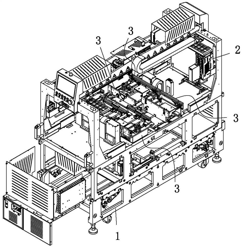
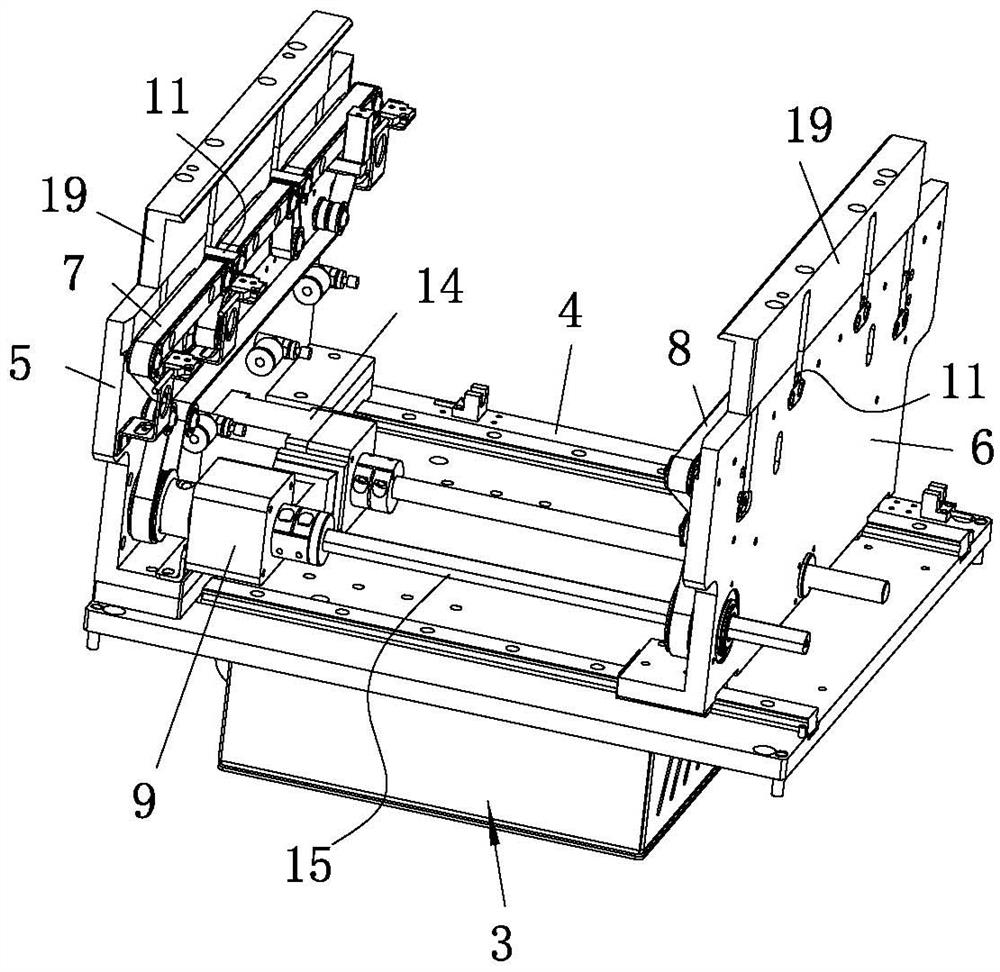
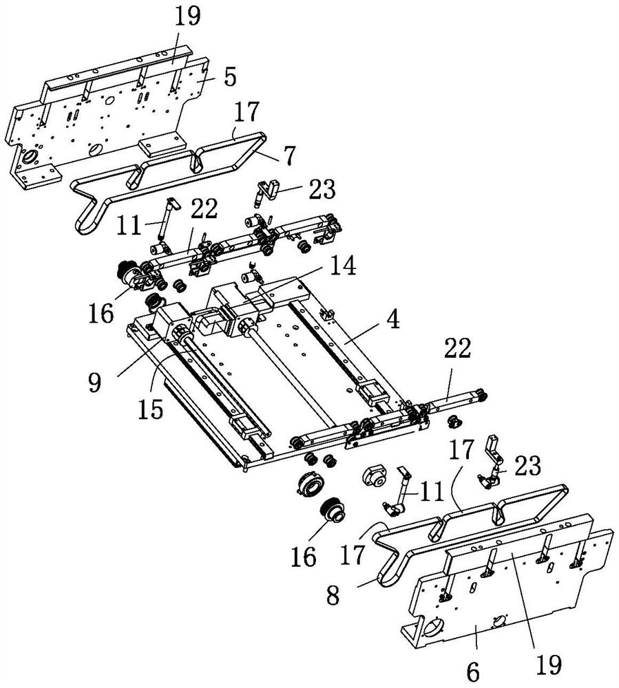
[0032] see Figure 1 to Figure 6 As shown, a multi-stage carrier cycle switching machine of the present invention includes a frame 1, a transfer mechanism 2 installed on the frame 1, and two conveying mechanisms 3, and the two conveying mechanisms 3 are respectively used to transfer the carrier Inputting and outputting the carrier, the transfer mechanism 2 is used to transfer the carrier between two conveying mechanisms 3 . In this embodiment, the frame 1 is welded by metal rods, and the transfer mechanism 2 and the delivery mechanism 3 are equipped with independent controllers, so that the transfer mechanism 2 and the delivery mechanism 3 become independent functional modules. The...


PUM


Abstract

The invention relates to the technical field of carrier transferring, and particularly discloses a multi-section type carrier circulation switching machine. The machine comprises a rack, a transferring mechanism and two conveying mechanisms, and the transferring mechanism transfers a carrier between the two conveying mechanisms. Each conveying mechanism comprises a base plate, a first supporting plate, a second supporting plate, a first annular belt, a second annular belt, a first driving part and two jacking units, wherein the first supporting plate and the second supporting plate are arranged on the base plate and are parallel to each other, the first annular belt and the second annular belt are rotationally arranged on the first supporting plate and the second supporting plate respectively, and the first driving part is used for driving the annular belts, and the two jacking units are arranged on the two supporting plates; and each supporting plate is provided with a first containing hole, and each jacking unit comprises a second driving part and a supporting plate connected with the second driving part. The supporting plates of the two jacking units abut against and support thetwo ends of the carrier correspondingly. The second driving parts are mounted in the first containing holes, so that the thickness is reduced, the structural design is simplified, and the miniaturization development trend is met; and the jacking units jack up the carrier, the annular belts continuously convey the carrier, the transferring mechanism circularly moves the carrier between the two conveying mechanisms, and the conveying efficiency of the carrier is improved.

Description

technical field [0001] The invention relates to the technical field of carrier transfer, and in particular discloses a multi-stage carrier cycle switching machine. Background technique [0002] During the use of materials, it is often necessary to process the materials in various processes. In order to improve the processing efficiency, it is often necessary to automatically transport the materials carried by the carrier. During the transportation of the carrier, sometimes the carrier needs to be stopped. Moving for processing, sometimes the carrier needs to be transferred in different positions. In the prior art, the design of the carrier’s conveying structure is unreasonable. When the carrier stops moving, the entire conveying system will stop, which is extremely inconvenient to use, resulting in the failure of the carrier. Cycle efficiency is low. In addition, the conveying system in the prior art is complex in design and thick in thickness, which is extremely inconvenie...

Claims


Application Information

Patent Timeline
IPC IPC(8): B65G47/90B65G47/91B65G23/04B66F11/00B66F13/00
CPCB65G23/04B65G47/901B65G47/912B66F11/00B66F13/00
Inventor 张世源林顺威
Owner DONGGUAN ANDA AUTOMATIC EQUIP
Why Eureka
Try Eureka