Assembly process of optical path module and special drying equipment
An assembly process and drying equipment technology, which is applied in metal processing equipment, drying, drying machines, etc., can solve the problems of time-consuming old, watermarks on the lens, etc.
- Summary
- Abstract
- Description
- Claims
- Application Information
AI Technical Summary
Problems solved by technology
Method used
Image
Examples
Embodiment 1
[0044] The invention provides an assembly process of an optical path module, such as figure 1 As shown it includes the following steps:
[0045] S1. Ultrasonic cleaning is performed on each component that constitutes the optical path module.
[0046] S2. Put the cleaned parts in an ultra-clean environment for drying; this drying refers to the removal of moisture on the surface of the parts to achieve drying, so it includes blowing to accelerate the air flow path to achieve accelerated drying, and also includes increasing the temperature Achieve accelerated drying.
[0047] S3. Assembling the dried components in an ultra-clean environment to form an optical path module.
[0048] As one of the preferred examples, the step S1 includes placing each component of the optical path module in batches or all in an ultrasonic water tank, and performing ultrasonic water washing through the ultrasonic water tank. The ultrasonic water tank is an existing common equipment for ultrasonic w...
Embodiment 2
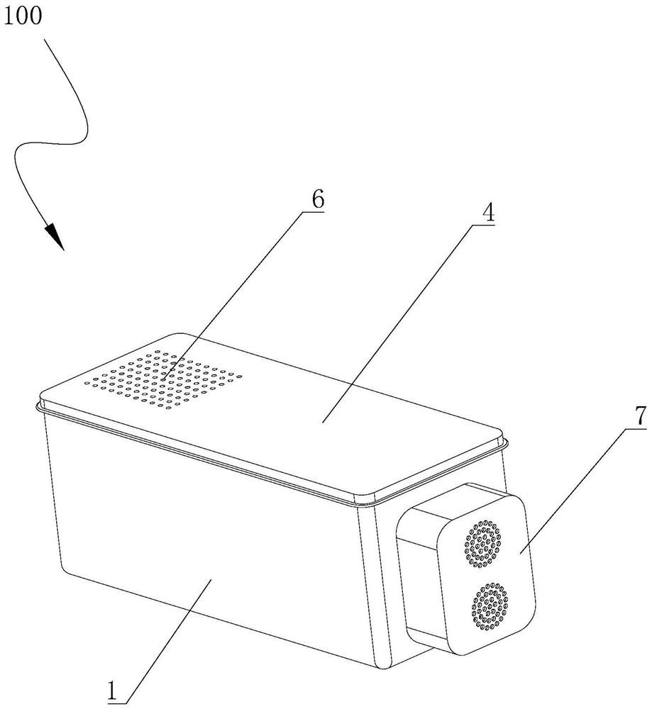
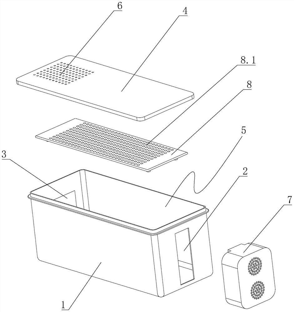
[0057] The basic structure is the same as that of Embodiment 1, the difference is that, as Figure 2-5 As shown, the special drying equipment 100 includes:
[0058] Housing 1, the housing 1 has a rectangular structure, and the two ends corresponding to the length direction L of the housing 1 are respectively provided with an air inlet 2 and a main air outlet 3;
[0059] Cover 4, the housing 1 is provided with an opening 5 matching the cover 4, the cover 4 covers the housing 1 and covers the opening 5, the position of the cover 4 close to the main air outlet 3 There is an upper air outlet 6;
[0060] A blower 7, the blower 7 is placed on the casing 1 and blows air into the casing 1 through the air inlet 2;
[0061] All parts to be dried are placed in the casing 1 and located on the airflow path between the air inlet 2 and the main air outlet 3 .
Embodiment 3
[0063]The basic structure is the same as that of the second embodiment, the difference is that: the casing 1 is provided with a shelf 8, and there is a gap between the shelf 8 and the bottom surface of the inner cavity of the casing 1, and the part of the shelf 8 The area is divided into a storage area for shelving parts, which can be a part of the upper end surface of the shelf 8, or extend to the entire upper end surface, and the upper end surface of the storage rack 8 is located in the storage area. Number of through holes 8.1. The setting of the through hole 8.1 can increase the loss of water dripping from the parts onto the shelf 8 through the through hole 8.1, and also increase the airflow loss between the parts and the shelf 8.
[0064] Preferably, a laying layer made of porous material is laid on the bottom of the casing 1, and the parts to be dried are placed on the laying layer.
PUM
 Abstract
Description
Claims
Application Information
 - R&D
- Intellectual Property
- Life Sciences
- Materials
- Tech Scout
- Unparalleled Data Quality
- Higher Quality Content
- 60% Fewer Hallucinations
Browse by: Latest US Patents, China's latest patents, Technical Efficacy Thesaurus, Application Domain, Technology Topic, Popular Technical Reports.
© 2025 PatSnap. All rights reserved.Legal|Privacy policy|Modern Slavery Act Transparency Statement|Sitemap|About US| Contact US: help@patsnap.com


