A shock-resistant turning tool

An anti-vibration car and tool technology, applied in the field of cutting, can solve the problems of inability to suppress the vibration of the workpiece itself, and the effect is minimal, and achieve the effect of solving the surface quality substandard, excellent surface quality and cutting accuracy, and obvious anti-vibration effect.

Active Publication Date: 2022-05-24
ZHUZHOU CEMENTED CARBIDE CUTTING TOOLS CO LTD
View PDF8 Cites 0 Cited by
  • Summary
  • Abstract
  • Description
  • Claims
  • Application Information

AI Technical Summary

Problems solved by technology

However, at present, the main source of vibration in the processing of thin-walled workpieces comes from the vibration of the workpiece itself due to the cutting force. That is to say, no matter how stable the cutting tool is, it cannot suppress the vibration of the workpiece itself, and the results obtained in turning thin-walled workpieces are minimal.

Method used


Image

  • A shock-resistant turning tool
  • A shock-resistant turning tool
  • A shock-resistant turning tool

Examples


Embodiment 1

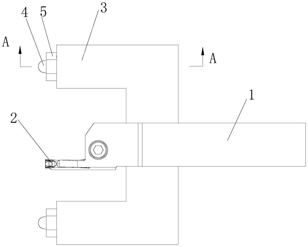
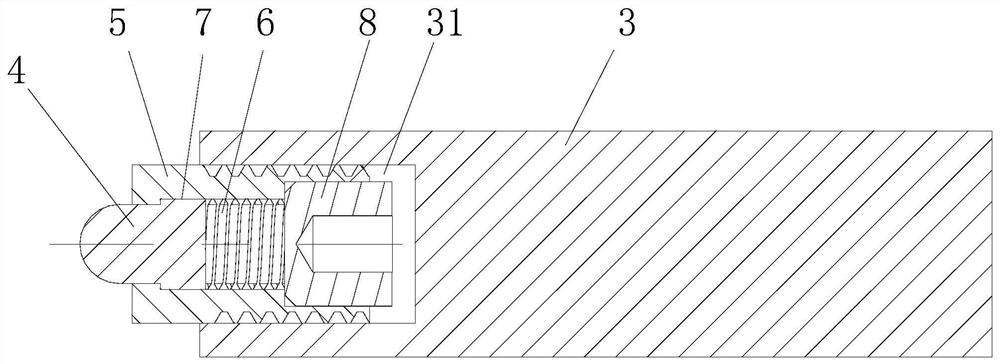
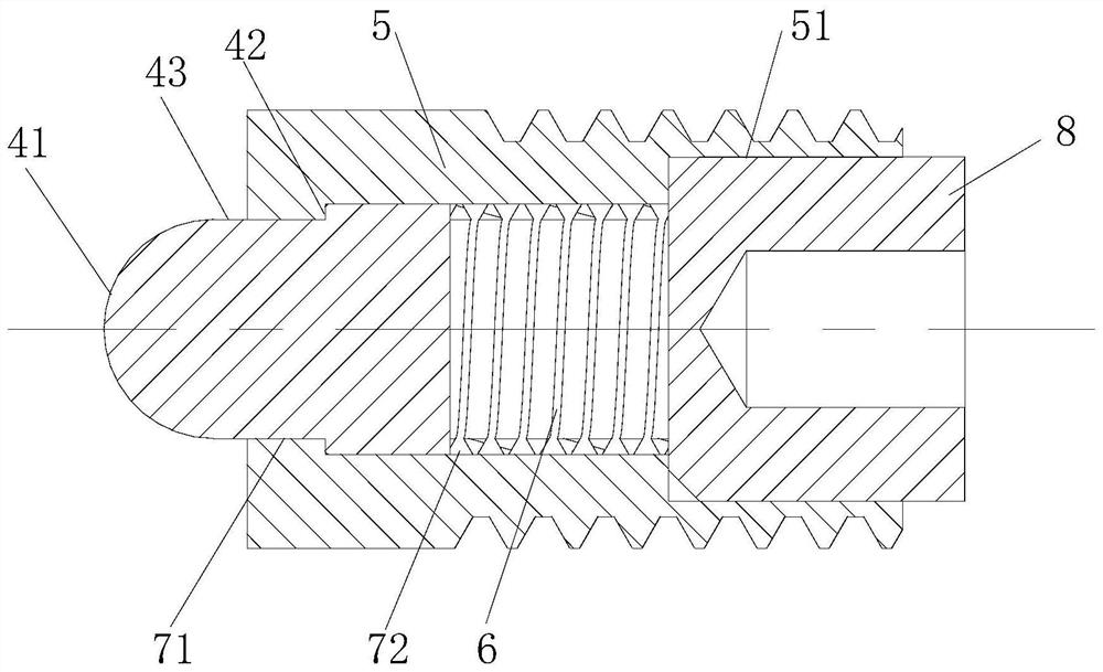
[0029] like Figure 1 to Figure 5 As shown, the anti-vibration turning tool of this embodiment includes a cutter body 1, a blade 2 and an anti-vibration assembly, the blade 2 is installed at the front end of the cutter body 1, and the anti-vibration assembly includes an anti-vibration arm 3, an anti-vibration compression member 4, a compression member base 5 and an elastic member 6. The anti-vibration arm 3 is installed on the cutter body 1, the pressure piece seat 5 is set at the front end of the anti-vibration arm 3, the pressure piece base 5 is provided with an installation groove 7, the anti-vibration pressure piece 4 and the elastic piece 6 are arranged in the installation groove 7, and The elastic member 6 is abutted between the anti-vibration compression member 4 and the groove bottom of the installation groove 7 , the front end of the anti-vibration compression member 4 is arranged outside the installation groove 7 , and an axial limit structure is arranged between the ...

Embodiment 2

[0039] like Figure 7 As shown, the anti-vibration turning tool of this embodiment differs from Embodiment 1 only in that:

[0040] In this embodiment, the insert 2 selects an external turning insert, and the principle of external turning is the same as that of face turning.

[0041] The remaining points that are not described are consistent with Embodiment 1, and are not repeated here.

Embodiment 3

[0043] The difference between the anti-vibration turning tool of this embodiment and Embodiment 1 is:

[0044] In this embodiment, the anti-vibration arm 3 is arranged on the cutter body 1 in an axially movable manner. By adjusting the axial displacement of the anti-vibration arm 3 on the cutter body 1 , the degree of contact between the spherical surface 41 of the anti-vibration compression member 4 and the workpiece 9 can be adjusted. In order to meet the anti-vibration requirements during cutting, the anti-vibration arm 3 can be adjusted so that the spherical surface 41 does not come into contact with the workpiece 9 when the anti-vibration is not required.

[0045] The remaining points that are not described are consistent with Embodiment 1, and are not repeated here.


PUM


Abstract

The invention discloses an anti-vibration turning tool, which comprises a tool body, a blade and an anti-vibration assembly. The blade is installed on the front end of the tool body. , the pressure piece seat is set at the front end of the anti-seismic arm, the pressure piece seat is provided with an installation groove, the anti-seismic pressure piece and the elastic piece are arranged in the installation groove, and the elastic piece is set between the anti-seismic pressure piece and the groove bottom of the installation groove, and the anti-seismic The front end of the pressure piece is arranged outside the installation groove and the front end of the anti-seismic pressure piece has a convex curved surface that can contact the workpiece before the blade, and there is an axial limit structure between the anti-seismic pressure piece and the installation groove to prevent the anti-seismic pressure piece from the installation groove. When the cutter body of the present invention advances and contacts the workpiece with the blade, the convex curved surface will slightly squeeze the workpiece, and the convex curved surface will shrink into the installation groove while slightly squeezing and supporting the workpiece, which can suppress the vibration of the workpiece to be processed, thereby achieving an anti-seismic effect.

Description

technical field [0001] The present invention relates to cutting, in particular to an anti-vibration turning tool. Background technique [0002] Among the tools used in metal processing today, especially in the field of parts turning, most manufacturers are always troubled when processing thin-walled workpieces. The quality is not ideal, so most manufacturers can only use the method of reducing the cutting parameters and reducing the cutting efficiency to make the processed parts meet the expected requirements as much as possible, but the results are often unsatisfactory, so a product that can be used in turning thin walls is introduced. Parts are turning tools that can effectively suppress vibration, which is very beneficial to the current machining market. [0003] The anti-vibration turning tool in the prior art is provided with an anti-vibration rubber ring in the anti-vibration component, which can effectively absorb shock, ensure stable cutting, and prevent the problem...

Claims


Application Information

Patent Timeline
Patent Type & Authority Patents(China)
IPC IPC(8): B23B27/00
CPCB23B27/002
Inventor 付宇鹏刘敏荣刚龚正
Owner ZHUZHOU CEMENTED CARBIDE CUTTING TOOLS CO LTD
Why Eureka
Try Eureka