Electric power steering device
A technology of electric power steering and electric motor, which is applied in the direction of power steering mechanism, electromechanical device, steering mechanism, etc., can solve the problems of limited space, no redundant system, etc., and achieve the effect of miniaturization
- Summary
- Abstract
- Description
- Claims
- Application Information
AI Technical Summary
Problems solved by technology
Method used
Image

Examples
Embodiment approach 1
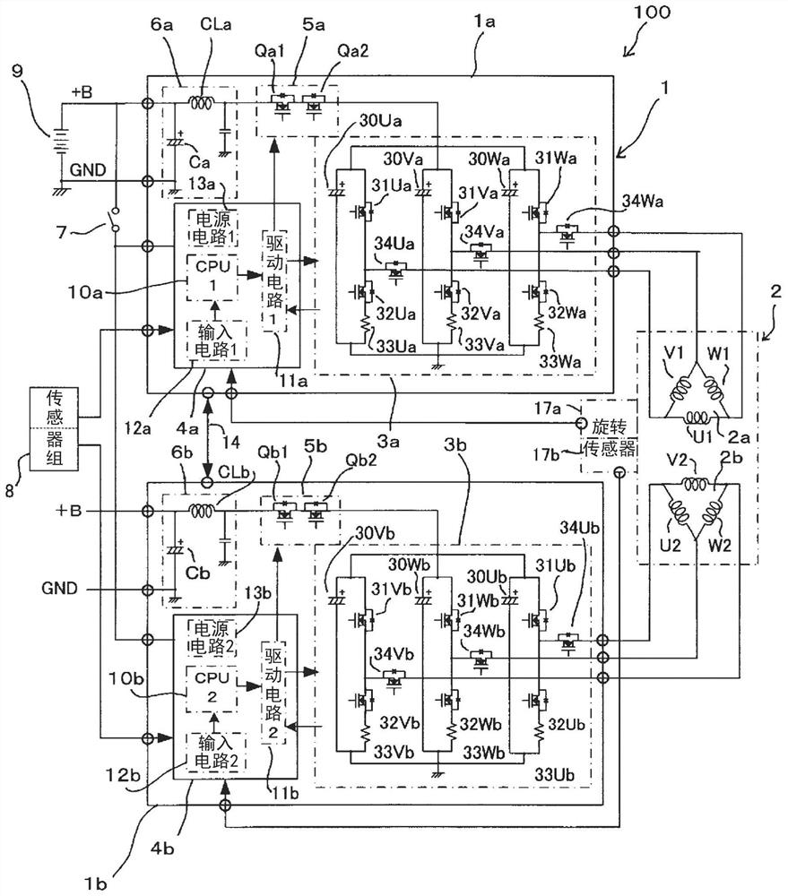
[0031] Next, an electric power steering device according to Embodiment 1 of the present application will be described with reference to the drawings. First, the circuit configuration of the electric power steering device according to Embodiment 1 will be described. figure 1 It is an overall circuit diagram of the electric power steering device according to the first embodiment. exist figure 1 Among them, an electric power steering apparatus 100 includes an electric motor 2 that generates an assist torque corresponding to a steering torque that a driver applies to a steering gear (not shown) of a vehicle, and a control unit 1 that controls the electric motor 2 .
[0032] The motor 2 is configured as a three-phase synchronous motor including a first armature winding 2a and a second armature winding 2b. The first armature winding 2 a and the second armature winding 2 b have substantially the same configuration, but are arranged with an electrical angle of 120 degrees shifted f...
Embodiment approach 2
[0109] Next, an electric power steering device according to Embodiment 2 will be described. Figure 6 It is a plan view showing the wall surface and its surroundings of the housing of the electric power steering device according to the second embodiment, which is different from that of the first embodiment described above. Figure 5 Corresponding. The overall circuit diagram and figure 1 same. exist Figure 6 In the case 1e, a first power module 3aa constituting a first inverter circuit 3a and a first power relay 5a, and a power module constituting a second inverter circuit 3b and a second power relay 5b are mounted on the bottom, that is, the inner wall surface of the casing 1e. The second power module is 3cc.
[0110] Here, the second power module 3cc is configured such that the lead-out positions of the power supply terminals 3cp and 3cn are different from the second power module 3bb in the first embodiment described above. That is, in Embodiment 1, it is derived from ...
Embodiment approach 3
[0120] Next, an electric power steering device according to Embodiment 3 will be described. Figure 7 It is a plan view showing the wall surface and its surroundings of the housing of the electric power steering device according to Embodiment 3, which is different from that in Embodiment 2 above. Figure 6 Corresponding. A first power module 3dd constituting the first inverter circuit 3a and the first power relay 5a, and a first power module 3d constituting the second inverter circuit 3b and the second power relay 5b are mounted on the inner wall surface of the bottom of the casing 1f. 2 power modules 3ee.
[0121] In Embodiment 3, only one power supply connector 40e is provided, and the +B line and the GND line of the battery 9 of the vehicle are connected to this one power supply connector 40e. were divided into two groups (not shown). Therefore, compared with Embodiment 1, 2, it is larger in size. In addition, the connector for a power supply has one housing, and the te...
PUM
 Abstract
Description
Claims
Application Information
 - R&D
- Intellectual Property
- Life Sciences
- Materials
- Tech Scout
- Unparalleled Data Quality
- Higher Quality Content
- 60% Fewer Hallucinations
Browse by: Latest US Patents, China's latest patents, Technical Efficacy Thesaurus, Application Domain, Technology Topic, Popular Technical Reports.
© 2025 PatSnap. All rights reserved.Legal|Privacy policy|Modern Slavery Act Transparency Statement|Sitemap|About US| Contact US: help@patsnap.com