
Inflatable and deflatable type sealed drift tube end

A drift tube, inflation and deflation technology, which is applied in the field of drift tube sealing, can solve the problems of easy breakage, irreparable, and invalidation of the drift tube, and achieve the effects of reducing disturbance, increasing life, and high positioning accuracy

Active Publication Date: 2021-03-26
CHINA INSTITUTE OF ATOMIC ENERGY
View PDF5 Cites 0 Cited by
  • Summary
  • Abstract
  • Description
  • Claims
  • Application Information

AI Technical Summary

Problems solved by technology

[0009] First, as the working time increases, the gas leakage in the pipe cannot be monitored. Since the entire gas port is sealed, it cannot be detected when the entire pipe is out of gas, that is to say, if the pipe air pressure decreases, the performance will decline The entire pipe can only be scrapped because it cannot be disposed of;
[0010] Second, because the anode wire is a thin wire with a diameter of 50 μm, it is easy to break during use. Once broken, the entire drift tube will be useless and cannot be repaired
[0011] Third, the working gas in the tube has a certain life span, beyond a certain working time will affect the test performance, but because the tube is fully sealed, the gas in the tube cannot be replaced

Method used


Image

  • Inflatable and deflatable type sealed drift tube end
  • Inflatable and deflatable type sealed drift tube end
  • Inflatable and deflatable type sealed drift tube end

Examples


Embodiment Construction

[0052] The present invention will be further described below in conjunction with the accompanying drawings and embodiments.

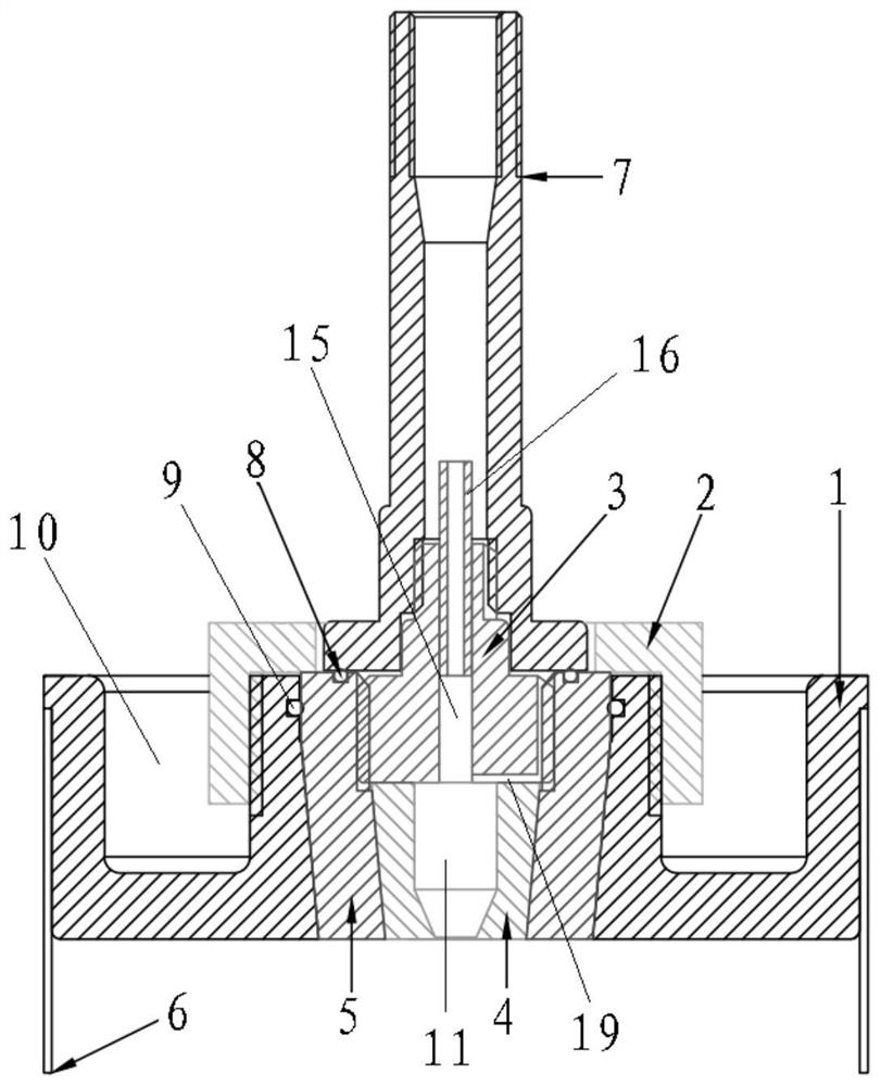
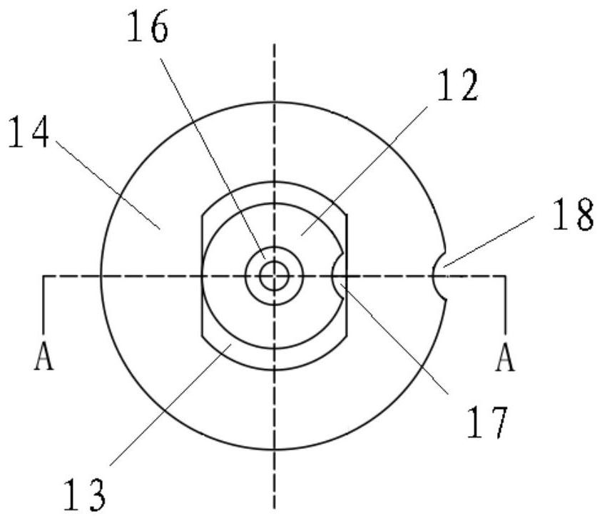
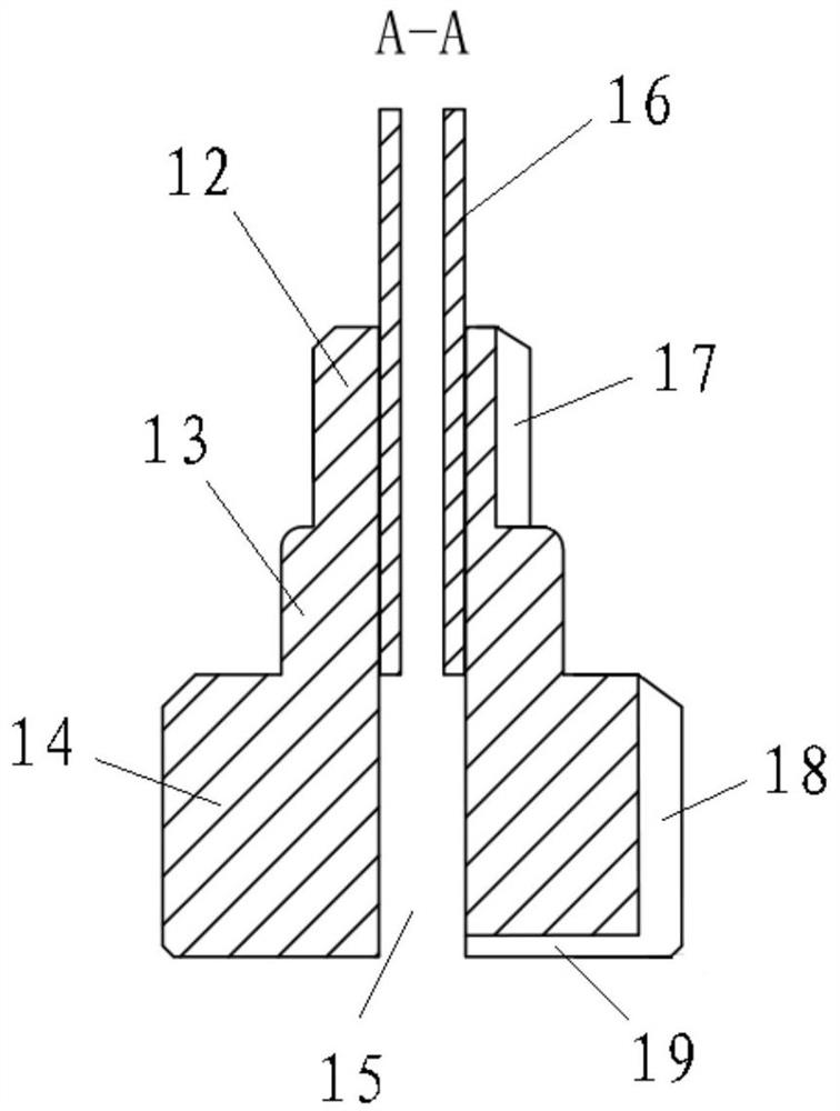
[0053] Such as figure 1 As shown, the end of a kind of inflatable and deflated airtight drift tube provided by the present invention is arranged on the port of the tube body 6 of the drift tube, wherein the port plate 1 (port Plate 1 plays the role of sealing the entire drift tube, fixing the anode wire, and connecting the tube body 6), the port plate 1 is disc-shaped, the center position is provided with a first through hole, and an adapter 3 is arranged in the first through hole, and also includes The gas nozzle 7 arranged on the adapter 3, the anode wire in the drift tube extends into the gas nozzle 7 through the adapter 3; the gas nozzle 7 can input working gas into the adapter 3 during the inflation operation, and the adapter 3 can transfer the working gas The flow rate is reduced and delivered to the tube body 6; after the inflation operation is...


PUM

PropertyMeasurementUnit
Side wall thicknessaaaaaaaaaa

Abstract

The invention belongs to the technical field of drift tube sealing, and particularly relates to an inflatable and deflatable type sealed drift tube end which is arranged in an end opening of a tube body (6) of a drift tube. The inflatable and deflatable type sealed drift tube end comprises an end opening plate (1), wherein the end opening plate (1) is arranged in the end opening and connected withthe end opening in a sealed mode, the end opening plate (1) is in a disc shape, a first through hole is formed in the center of the end opening plate (1), and an adapter (3) is arranged in the firstthrough hole. The inflatable and deflatable type sealed drift tube end further comprises a gas nozzle (7) which is arranged on the adapter (3), and an anode wire in the drift tube stretches into the gas nozzle (7) through the adapter (3). When inflation operation is conducted, the gas nozzle (7) can input the working gas into the adapter (3), and the adapter (3) can reduce the flow speed of the working gas and convey the working gas into the pipe body (6). After the inflation operation is accomplished, the gas nozzle (7) can be kept in a sealed state. According to the inflatable and deflatabletype sealed drift tube end, the high sealing performance and the high-voltage insulation resistance are provided for the drift tube, the high positioning precision is provided for the assembly of theanode wire, the anode wire can be replaced, and all functions required by inflation, deflation and gas keeping are fulfilled.

Description

technical field [0001] The invention belongs to the technical field of drift tube sealing, in particular to an inflatable and deflated sealed drift tube end. Background technique [0002] Cosmic ray muon imaging technology is a new type of non-destructive imaging technology developed in recent years. It uses natural cosmic rays as the ray source and avoids the impact of radiation on the inspected objects and operators caused by external artificial ray sources. In addition, cosmic ray muons have strong penetrating ability and are sensitive to high atomic number (high Z) materials. These characteristics make this technology have advantages in non-destructive imaging of heavy nuclear materials, and are used in nuclear security, nuclear waste measurement, and treaty verification. The field has broad application prospects. [0003] The principle of cosmic ray μ imaging for detecting fissile nuclear materials is based on measuring the deflection angle of the cosmic ray μ passing ...

Claims


Application Information

Patent Timeline
IPC IPC(8): F16L19/065F16L55/02G01T7/00
CPCF16L19/065F16L55/02G01T7/00
Inventor 汤秀章陈欣南
Owner CHINA INSTITUTE OF ATOMIC ENERGY
Learn More