
Beam upturning joint structure with good anti-cracking performance and construction method thereof

A technology of crack resistance and joint structure, which is applied to the processing of building components, building structures, and building materials. It can solve problems such as rusting of steel bars and unfavorable mechanical properties of beams, and achieve enhanced connection performance, enhanced crack limitation, and ease The effect of the difference in bending stiffness

Active Publication Date: 2021-03-26
TONGJI UNIV ARCHITECTURAL DESIGN INST GRP CO LTD
View PDF6 Cites 0 Cited by
  • Summary
  • Abstract
  • Description
  • Claims
  • Application Information

AI Technical Summary

Problems solved by technology

This situation is detrimental to the mechanical performance of the beam
[0005] There is no special anchorage requirement for the longitudinal reinforcement of the upturned joint of the beam at the support, especially when the height of the upturned joint is high, the joint at the end of the beam will crack significantly under the action of negative bending moment, even if the crack does not disappear in a short period of time. Does not affect the safety of the structure, but the steel bars in the upturned joints will rust if they are exposed to the air for a long time

Method used


Image

  • Beam upturning joint structure with good anti-cracking performance and construction method thereof
  • Beam upturning joint structure with good anti-cracking performance and construction method thereof
  • Beam upturning joint structure with good anti-cracking performance and construction method thereof

Examples


Embodiment Construction

[0061] The technical solution of the present invention will be further described below in conjunction with the accompanying drawings.

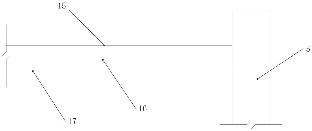
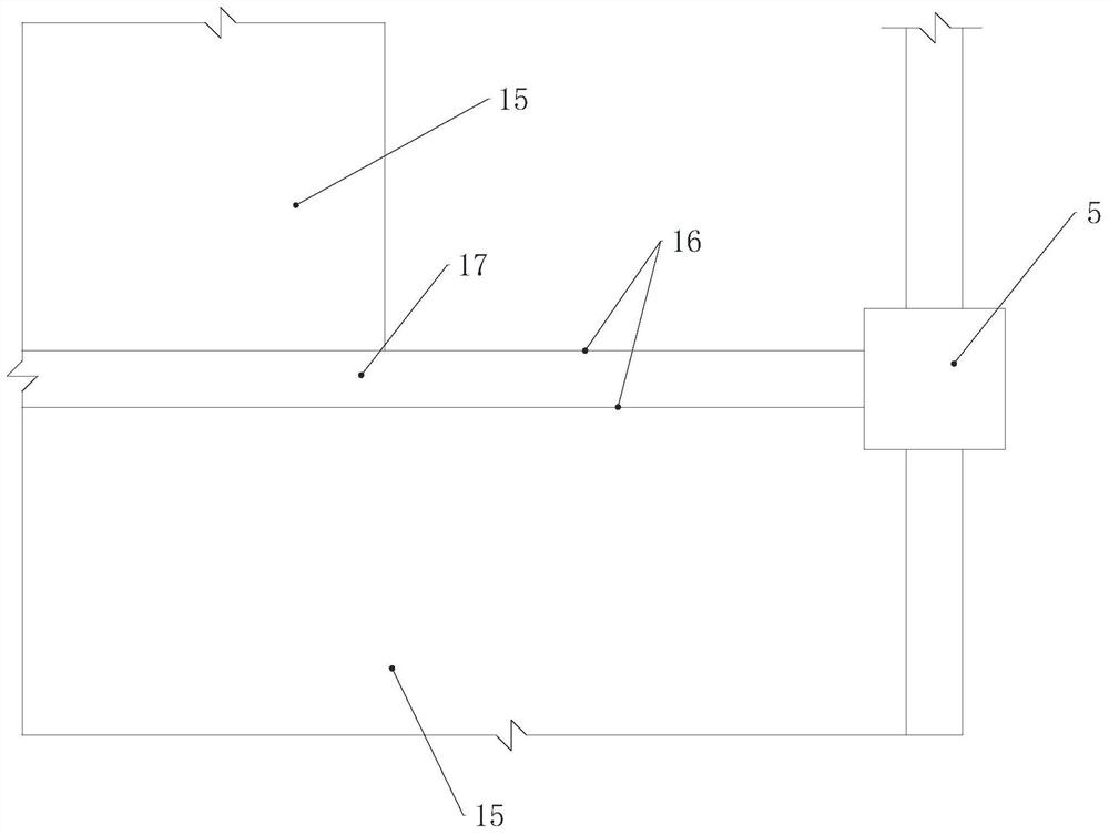
[0062] Such as figure 1 As shown, an upturned beam node structure with good crack resistance in the present invention includes a constant slab 1 , a constant beam 2 , a raised slab 3 , an upturned beam 4 and a beam support 5 . The regular slab 1 is the floor slab of normal elevation, the regular beam 2 is used to support the regular slab 1 which matches with the regular slab 1, the rising slab 3 is the floor slab at the normal elevation, and the upturning beam 4 is used to support the rising slab 3, the beam bottom of the upturned beam 4 is flush with the bottom of the regular beam, and the beam top elevation of the upturned beam 4 is higher than that of the regular beam top. The beam support 5 is connected with the upturned beam and the normal beam.

[0063] Inside the upturning beam 4, there are several channel steels 6 arranged in sequenc...


PUM


Abstract

The invention discloses a beam upturning joint structure with good anti-cracking performance and a construction method thereof. The beam upturning joint structure comprises a constant plate, a constant beam used for supporting the constant plate, a lifting plate higher than the constant plate in elevation, an upturning beam used for supporting the lifting plate, and a beam support used for connecting the upturning beam and the constant beam, wherein the beam bottom of the upturning beam is flush with the beam bottom of the constant beam, and the beam top elevation of the upturning beam is higher than the beam top elevation of the constant beam; and a plurality of steel channels are sequentially arranged in the upturning beam in the extending direction of the upturning beam, upper flanges and lower flanges of the steel channels face the beam bottom and the beam top of the upturning beam correspondingly, meanwhile, split bolts are arranged between the upper flanges and the lower flangesin an oppositely penetrating mode, the limb tips of the steel channels face one side of the lifting plate, and holes for allowing steel bars in the constant plate to penetrate through are formed in aweb. By arranging the steel channels, the development of cracks can be limited, and stirrups can be helped to resist the torque caused by the bending moment of the plate end to a certain extent; and the holes of the steel channels can enhance the connecting performance of the plate and beam concrete, and the plate steel bars can pass through the holes to be prevented from being broken.

Description

technical field [0001] The invention relates to an upturned node structure, in particular to a beam upturned node structure with good crack resistance and a construction method thereof. Background technique [0002] In the design of floor slab structure, due to the requirements of construction or equipment specialization, we often encounter the situation of "lifting the slab", that is, it is necessary to raise the structural elevation of a certain floor slab, which is higher than the slab elevation of the normal floor. The beam level connected to the floor slab is raised accordingly. However, if the beam passes through both the slab with normal slab elevation and the slab after the "lifted slab", at this time, the general situation will be to choose the elevation of the beam top at the normal slab surface, and select the beam upturned node at the "lifted slab" method; sometimes the method of folded beams is also chosen, but the folded beams not only have the disadvantages o...

Claims


Application Information

Patent Timeline
Patent Type & Authority Applications(China)
IPC IPC(8): E04G21/00E04B1/20E04B1/21E04B5/32E04G21/02E04G13/04E04G11/36
CPCE04G21/00E04B1/20E04B1/21E04B5/32E04G21/02E04G13/04E04G11/36
Inventor 毛范燊曹炜成戎刘东王妍郁欣捷
Owner TONGJI UNIV ARCHITECTURAL DESIGN INST GRP CO LTD
Learn More