Hydraulic Anchor Head of Multipoint Displacement Meter and Its Fixing Method

A technology of displacement meter and anchor head, which is applied in foundation structure test, on-site foundation soil survey, construction, etc. It can solve problems such as long grouting time, irregular shape of pre-buried holes, inconvenient operation, etc., and achieve anti-skid ability Strong, good anchoring effect, simple structure

Active Publication Date: 2021-08-03
四川高速公路建设开发集团有限公司
View PDF0 Cites 0 Cited by
  • Summary
  • Abstract
  • Description
  • Claims
  • Application Information

AI Technical Summary

Problems solved by technology

These anchoring methods are limited by the technical level of engineering construction and have many shortcomings.
For example, compressed wood anchoring is difficult to install in soil anchoring, inconvenient to operate, difficult to control the water injection time and expansion time, and the anchoring strength of the soil is not enough, which will easily cause the measurement points in the hole to move, making the monitoring data inaccurate; using grouting or anchoring When anchoring with agent, the grouting time is long, the construction is inconvenient, and the anchoring effect is not good in the extremely soft soil layer, resulting in unreliable anchoring strength, resulting in measurement errors and affecting the accuracy of the data
[0004] However, during the process of drilling the pre-buried hole, the shape of the pre-buried hole may be irregular, which makes it difficult for the hydraulic anchor head to be stably fixed in the pre-buried hole. If there is no change in the depth of the measured structure, the hydraulic anchor The head is not completely fixed and moves, which makes the measuring rod move and causes the measurement results of the multi-point displacement meter to be wrong, and it is difficult to ensure the accuracy of the multi-point displacement meter measurement

Method used


Image

  • Hydraulic Anchor Head of Multipoint Displacement Meter and Its Fixing Method
  • Hydraulic Anchor Head of Multipoint Displacement Meter and Its Fixing Method
  • Hydraulic Anchor Head of Multipoint Displacement Meter and Its Fixing Method

Examples


Embodiment Construction

[0036] The technical solutions of the present invention will be clearly and completely described below in conjunction with the embodiments. Apparently, the described embodiments are only some of the embodiments of the present invention, not all of them. Based on the embodiments of the present invention, all other embodiments obtained by those skilled in the art without making creative efforts belong to the protection scope of the present invention.

[0037] refer to Figure 1-7, the present invention provides a technical solution:

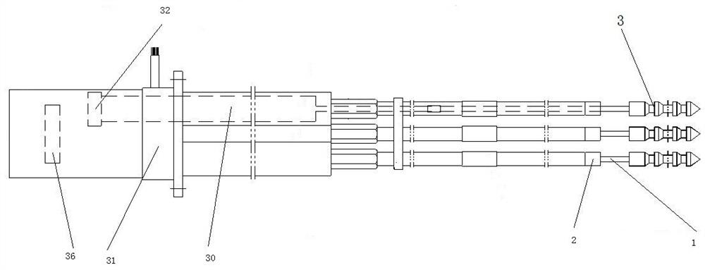
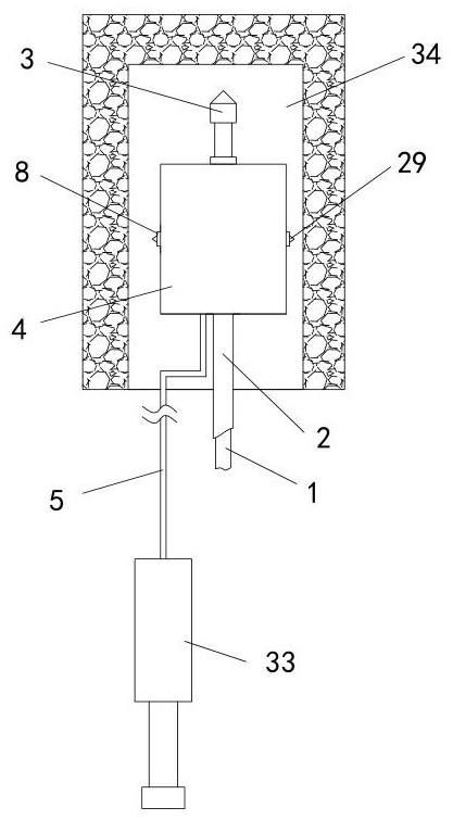
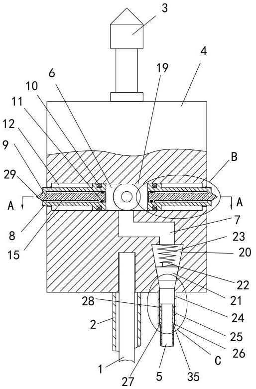
[0038] The hydraulic anchor head of the multi-point displacement meter, including the measuring rod 1, the protective tube 2, the anchor head 3, the fixed housing 4, the fixed assembly, the oil delivery pipe 5, the quick connection assembly for oil delivery and the anti-backflow assembly, and the middle part of one end of the fixed housing 4 A measuring rod 1 is fixedly installed, and the outer side of the measuring rod 1 is provided with a protec...


PUM


Abstract

The invention discloses a hydraulic anchor head of a multi-point displacement meter, which includes a fixing assembly, a protective tube is sheathed on the outer side of a measuring rod, the end of the protective tube is in clearance fit with a fixed casing, and an anchor head is arranged in the middle of the other end of the fixed casing. , the inside of the fixed housing is provided with a pressure chamber, the pressure chamber is connected with one end of the inner pipe, the other end of the inner pipe is connected with the anti-backflow assembly arranged inside the fixed casing, and the anti-backflow assembly is connected with the output pipe arranged on the fixed casing The oil quick-connect assembly is connected, the oil delivery quick-connect assembly is connected with the oil delivery pipe, and the fixed housing is provided with at least two opposite fixed assemblies, one end of each fixed assembly communicates with the pressure chamber, and the other end of the fixed assembly extends to the fixed housing Each displacement sensor of this multi-point displacement meter is provided with a hydraulic anchor head, and each hydraulic anchor head is provided with a fixed component, so that the displacement sensor can accurately measure the amount of change and obtain accurate result.

Description

technical field [0001] The invention relates to the technical field of geotechnical engineering monitoring, in particular to a hydraulic anchor head of a multi-point displacement meter and a fixing method thereof. Background technique [0002] The vibrating wire multi-point displacement meter is suitable for long-term buried in hydraulic structures or structures such as earth dams, earth embankments, slopes, tunnels, etc., to measure the displacement, settlement, strain, slip, etc. The temperature at the buried point can be measured simultaneously. When the measured structure is displaced and deformed, the anchor head of the multi-point displacement meter will drive the measuring rod, and the measuring rod will pull the pull rod of the displacement meter to generate displacement and deformation. A hydraulic anchor head is installed at the end of the measuring rod. They are fixed in the pre-buried holes. The displacement and deformation of the pull rod of the displacement m...

Claims


Application Information

Patent Timeline
Patent Type & Authority Patents(China)
IPC IPC(8): E02D33/00E02D1/00
CPCE02D1/00E02D33/00
Inventor 白皓张国强许圣祥向宝山王飞冉光炯周栓科王海宇曾楠
Owner 四川高速公路建设开发集团有限公司
Why Eureka
Try Eureka