


Quick Research
Generate reliable direction feasibility study reports for your R&D in just a few steps.

Technical Q&A
Discover and master advanced knowledge NOW. Basics, ideas, possibilities, all at once.

Find Solutions
As an expert in R&D theories, this can generate solutions to your technical problems instantly.

Evaluate Feasibility
Analyze your overall solution with one click, know your potential R&D risks in advance.

Monitor Landscape
Get weekly tech updates, stay abreast of the latest tech innovations and key insights.
Milling machine for metal shaft machining
A technology for metal shafts and milling machines, which is applied to metal processing equipment, metal processing machinery parts, milling machine equipment, etc., and can solve problems such as operators accidentally touching the handwheel and workpiece damage
- Summary
- Abstract
- Description
- Claims
- Application Information
AI Technical Summary
Problems solved by technology
Method used
Image

Examples
Embodiment 1
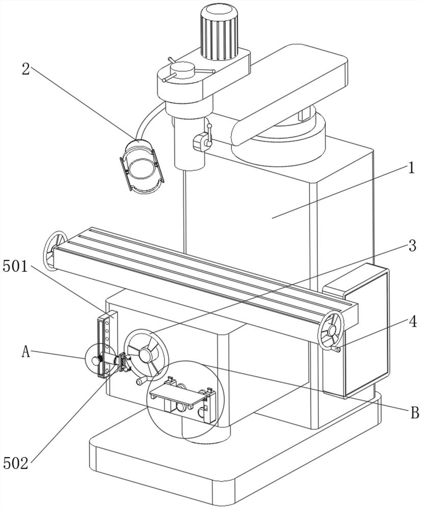
[0030] Example 1, such as Figure 1-6As shown, the present invention provides a milling machine for metal shaft processing, including a body 1 and a clamping device 5 , one end of the body 1 is rotatably connected to a hand wheel 3 , and a handle 4 is welded on the surface of the hand wheel 3 .
[0031] Let's talk about the specific setting and function of its clamping device 5 and dismantling device 6 in detail below.
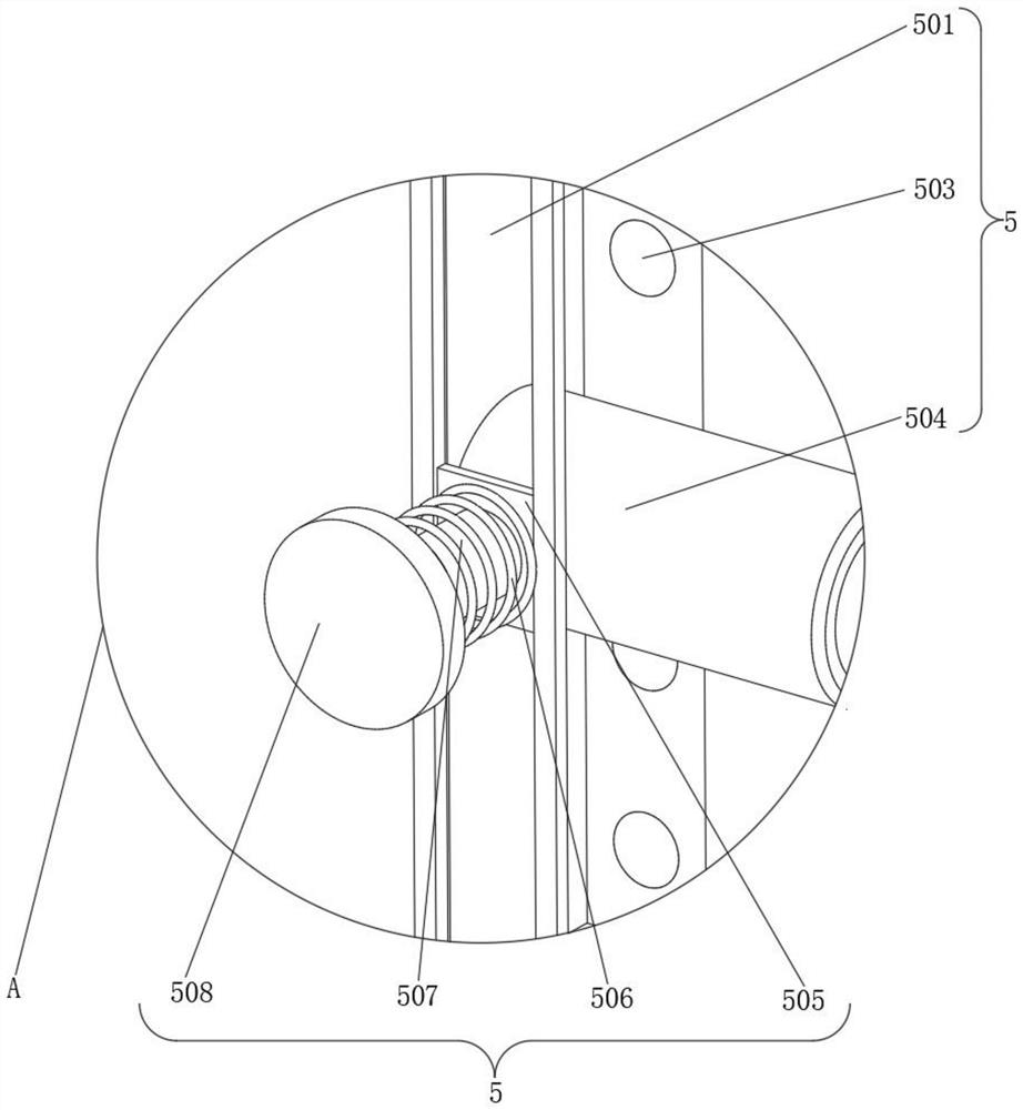
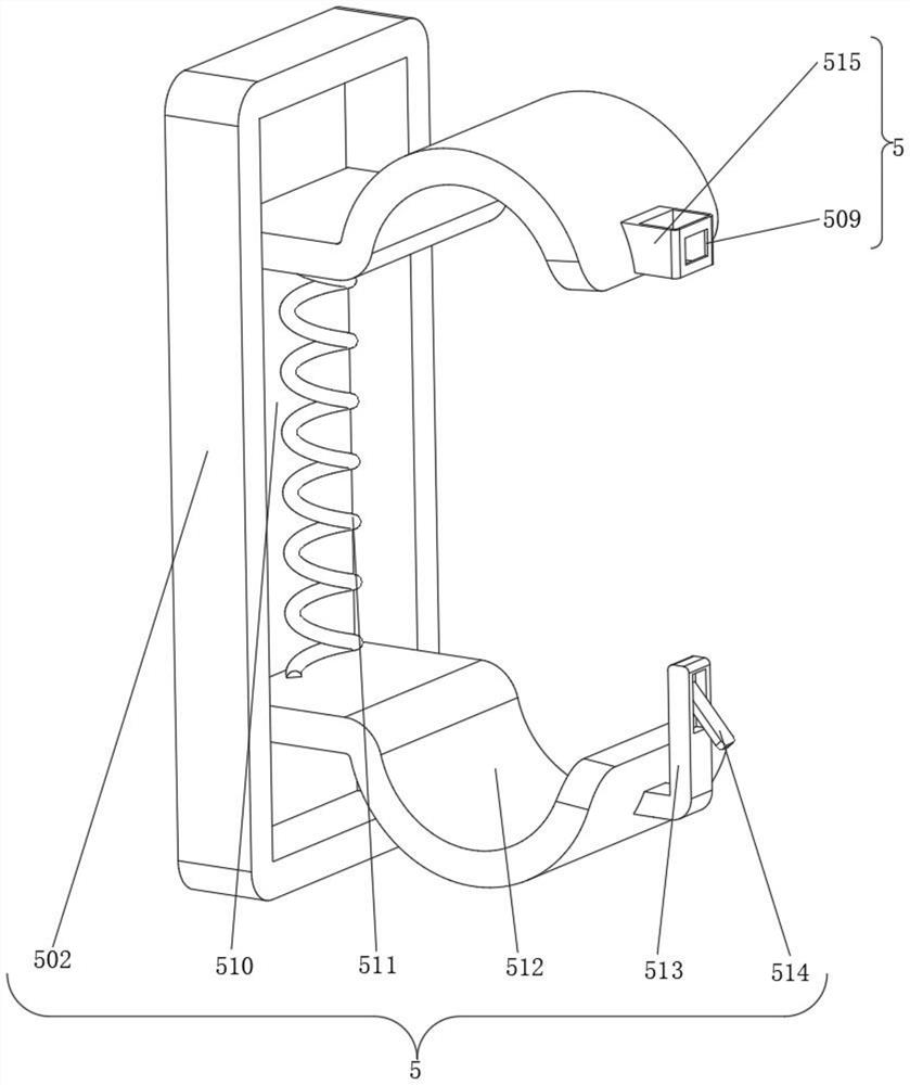
[0032] Such as figure 1 and image 3 As shown, one end of the body 1 is provided with a clamping device 5, the clamping device 5 includes a rectangular block 501, one end of the rectangular block 501 is welded to the body 1, and one end of the rectangular block 501 close to the handwheel 3 is provided with a groove, and the groove slides Connected with a first telescopic rod 504, the first telescopic rod 504 is composed of two hollow rods of different sizes, and the surface of the small rod is slidably connected inside the large rod, and the side wall of the...
Embodiment 2
[0036] Embodiment 2, on the basis of embodiment 1, as Figure 7 and Figure 8 As shown, one end of the body 1 is provided with a button 8, and one end of the body 1 is provided with a protective device 7, and the protective device 7 includes two protrusions 71, and the two protrusions 71 are distributed symmetrically with the central axis of the button 8, and the two protrusions One end of the block 71 away from the body 1 is provided with a draw-in groove 72, and one end of the two projections 71 close to each other is fixedly connected to the rotating shaft, and the surface of the rotating shaft is covered with a protective plate 74, which is rotationally connected with the rotating shaft, and the protective plate 74 is close to the rotating shaft. One end of the projection 71 is fixedly connected with a block 75, the size of the block 75 matches the size of the slot 72, and the end of the projection 71 close to the protective plate 74 is provided with a groove, and the seco...
PUM
 Abstract
Description
Claims
Application Information
 - R&D Engineer
- R&D Manager
- IP Professional
- Industry Leading Data Capabilities
- Powerful AI technology
- Patent DNA Extraction
Browse by: Latest US Patents, China's latest patents, Technical Efficacy Thesaurus, Application Domain, Technology Topic, Popular Technical Reports.
© 2024 PatSnap. All rights reserved.Legal|Privacy policy|Modern Slavery Act Transparency Statement|Sitemap|About US| Contact US: help@patsnap.com