
Voice time slot allocation and voice data sending method based on virtual link

A time slot allocation and voice data technology, which is applied in the field of data link network, can solve the problems of large transmission delay, poor network expansion capability, waste of time slot resources, etc., achieve reliable transmission performance and improve resource utilization

Active Publication Date: 2021-03-23
NO 20 RES INST OF CHINA ELECTRONICS TECH GRP
View PDF9 Cites 0 Cited by
  • Summary
  • Abstract
  • Description
  • Claims
  • Application Information

AI Technical Summary

Problems solved by technology

[0003] In the above network, the TDMA protocol with fixed allocation of time slots will increase the transmission delay as the network scale increases, and the network expansion ability is poor.
This protocol is only suitable for networks with relatively simple network topology. When it is used in complex environments such as land, due to problems such as occlusion, movement, coverage, and network topology changes, it is impossible to pre-allocate time slots to meet the multi-level relay of the link. need
And some services (such as voice) have special requirements on delay and jitter. If fixed allocation of service time slots is used, when there is no such service transmission, time slot resources will be wasted
In view of the shortcomings of fixed time slot allocation, although some scholars have proposed some dynamic voice time slot allocation algorithms, these dynamic allocation methods only allocate time slots for nodes, and fail to start from the entire link to ensure the time delay of the entire link of the distributed network. and jitter requirements
And when the network topology changes, the dynamically allocated time slots need to re-allocate time slot resources in order to meet the delay and other requirements, resulting in unstable service transmission

Method used


Image

  • Voice time slot allocation and voice data sending method based on virtual link
  • Voice time slot allocation and voice data sending method based on virtual link
  • Voice time slot allocation and voice data sending method based on virtual link

Examples


Embodiment Construction

[0041] The present invention will be further described below in conjunction with the accompanying drawings and embodiments.

[0042] The invention designs a method for dynamically allocating voice time slots based on a virtual link.

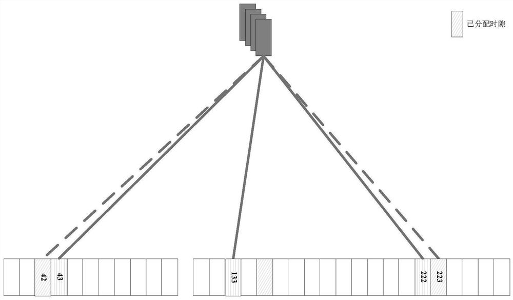
[0043] In the actual project, 3 time slot groups are allocated to the link, and each time slot group is allocated 3 time slots per second to ensure that the 2-hop link meets the voice delay and jitter requirements of 350 milliseconds and meets the needs of voice communication in most scenarios . When the voice link is longer than 3 hops, nodes with more than 3 hops multiplex time slots, and the voice delay increases by 110 milliseconds for each additional hop in the link, which not only saves time slot resources, but also meets the needs of voice services with more than 3 hops.

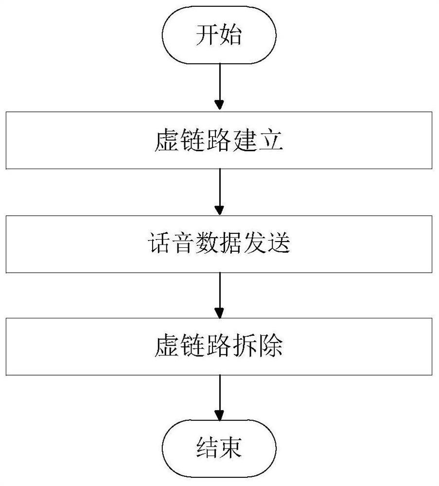
[0044] figure 1 Be the method flowchart of the present invention, below in conjunction with figure 2 The specific implementation method of the present invention is i...


PUM


Abstract

The invention provides a voice time slot allocation and voice data sending method based on a virtual link. The method comprises the following steps: dynamically establishing a virtual link from a source node to a destination node, only allocating time slots to nodes within a two-hop range in a link establishment process, and allocating time slots to nodes beyond two hops by multiplexing time slotresources allocated by the two-hop nodes. And the allocated time slot resources are not bound with the nodes and are only related to the hop count, so that the link intermediate network topology is changed, and the resources do not need to be reallocated. According to the invention, the time slot resources can be automatically allocated to the link according to the service requirements, the allocated time slot resources meet the time delay and jitter requirements of the service, and the resource utilization rate is improved; besides, the time slot resource allocated by the method is not boundwith the node and is only related to the hop count, the link intermediate network topology is changed, the resource does not need to be reallocated, the voice transmission quality is effectively ensured, and the utilization rate of the time slot resource is improved.

Description

technical field [0001] The invention relates to the technical field of data link network, in particular to a virtual link-based dynamic time slot allocation and voice data transmission method in a multi-hop network. Background technique [0002] The data link network is a centerless, distributed network architecture, which requires ensuring that services are delivered to the destination node reliably and quickly. In order to ensure that the transmission time slots of each user do not collide, the existing Link16 data link network needs to pre-allocate fixed transmission time slots, relay time slots, etc., and members send data in their pre-allocated fixed time slots. [0003] In the above-mentioned network, the TDMA protocol for fixedly allocating time slots increases the transmission delay as the network scale increases, and the network expansion capability is poor. This protocol is only suitable for networks with relatively simple network topology. When used in complex en...

Claims


Application Information

Patent Timeline
Patent Type & Authority Applications(China)
IPC IPC(8): H04W28/02H04W72/04H04W72/10H04W76/10
CPCH04W28/0231H04W76/10H04W72/0446H04W72/56
Inventor 石伟明史明伟陈卫卫万佳君
Owner NO 20 RES INST OF CHINA ELECTRONICS TECH GRP
Learn More