Multi-loop combined power distribution switch and working method thereof

A power distribution switch and multi-circuit technology, applied in substation/power distribution device housing, electrical components, circuit devices, etc., can solve the problems of large space occupation, high cost, limited equipment installation space, etc., and achieve convenient centralized control and guarantee The effect of stability and convenient wiring

Pending Publication Date: 2021-03-19
CHANGZHOU LIANLI AUTOMATION TECH
View PDF0 Cites 0 Cited by
  • Summary
  • Abstract
  • Description
  • Claims
  • Application Information

AI Technical Summary

Problems solved by technology

[0004] 1. The existing power distribution switches are mainly single-way switches, and there are many equipments used in underground coal mines. If a single-way power distribution switch is used, the number of equipment is large and the cost is high. wire, not convenient for wiring and operation control
[0005] 2. Originally, the quantity used in each area is large, and it is very time-consuming and laborious to move and disassemble again. Moreover, the installation space of the equipment is limited, and the existing installation and connection methods occupy too much space
[0006] 3. The existing power distribution switch technology is relatively old, and the degree of automation and intelligence is not high, which cannot meet the needs of existing digital mines

Method used


Image

  • Multi-loop combined power distribution switch and working method thereof
  • Multi-loop combined power distribution switch and working method thereof
  • Multi-loop combined power distribution switch and working method thereof

Examples


Embodiment 1

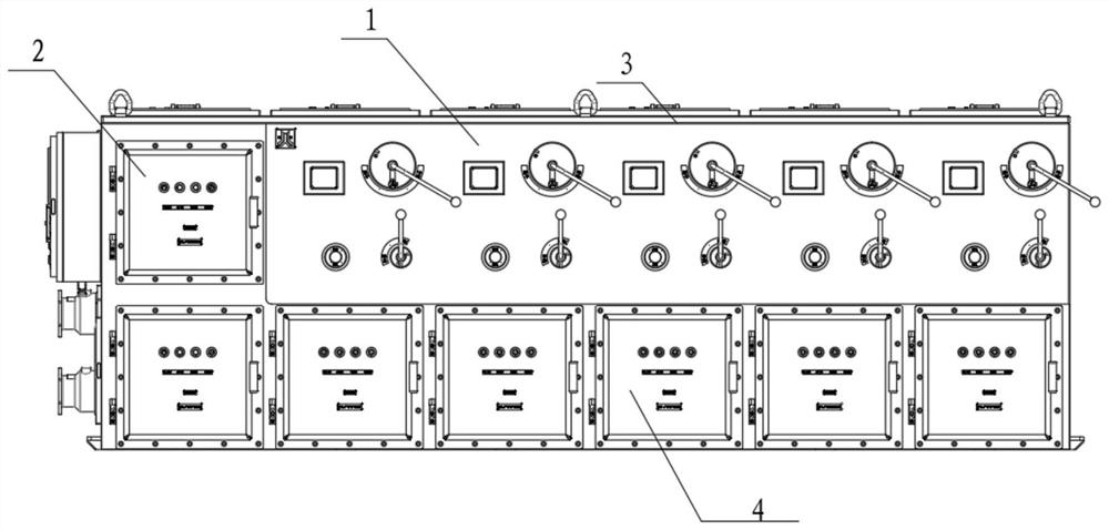
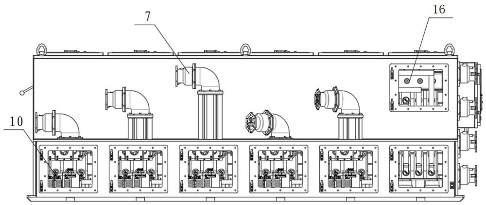
[0041] see Figure 1 to Figure 5 , a multi-circuit combined power distribution switch according to a preferred embodiment of the present invention, including a flameproof enclosure 1, a wiring cavity 5 and a plurality of vertically arranged input cable leads are arranged on the left side of the flameproof enclosure 1 Device 6, the rear top of the flameproof enclosure 1 is provided with a plurality of output cable lead-in devices 7;

[0042] The lower half of the flameproof enclosure 1 includes an incoming line chamber 16 and a plurality of output circuit chambers 4 from left to right, each output circuit chamber 4 is equipped with an output circuit breaker unit 9, and the output circuit breaker The output end of the unit 9 is output through the output cable lead-in device 7 for the use of load equipment, and the incoming line circuit breaker unit 8 with multiple parallel connections is installed in the inlet cavity 16, and the power is connected from the outside through the in...


PUM


Abstract

The invention relates to a multi-loop combined power distribution switch and a working method thereof, and belongs to the technical field of power supply and distribution, communication and automaticcontrol. The multi-loop combined power distribution switch comprises an explosion-proof shell, the left side of the explosion-proof shell is provided with a wiring cavity and a plurality of verticallyarranged input cable leading-in devices, and the top of the rear side of the explosion-proof shell is provided with a plurality of output cable leading-in devices. The explosion-proof shell internally comprises a wire inlet cavity and a plurality of output loop cavities, each output loop cavity is internally provided with an output circuit breaker unit, the output end of each output circuit breaker unit is output through an output cable leading-in device to be used by load equipment, and the wire inlet cavity is internally provided with a plurality of wire inlet circuit breaker units which are connected in parallel. A power supply is connected from the outside through an input cable leading-in device, a load switch is installed on each output loop cavity, a transformer is installed on theleft side of each load switch, a detection and control protection unit is installed on the left side wall of each output loop cavity, and a communication unit is further installed in each detection and control protection unit.

Description

technical field [0001] The invention relates to a multi-circuit combined power distribution switch and its working method, in particular to the technical fields of power supply and distribution, communication, and automatic control, in particular to a power distribution switch applied in the field of coal mines, which is installed underground in coal mines for power supply Power supply and protection for various electrical equipment in the area. Background technique [0002] With the development of science and technology, coal mining technology is also constantly improving, and there are more and more mining equipment in coal mines, which are more and more high-end, which puts forward higher requirements for the equipment that supplies power to it. In this context, all major coal mines have put forward requirements for the integration and intelligence of coal mines. [0003] At present, the distribution switches used in coal mines mainly have the following problems: [000...

Claims


Application Information

Patent Timeline
Patent Type & Authority Applications(China)
IPC IPC(8): H02B1/26H02B1/20H02J9/06
CPCH02B1/20H02B1/26H02J9/06
Inventor 王海军孙卓
Owner CHANGZHOU LIANLI AUTOMATION TECH
Why Eureka
Try Eureka